Module Settings
28
SW2 DIP Switch Node Address Setting on Main Fire Alarm Module
Refer to table in Appendix for Node Address Setting. Available addresses are 1 to 63. DIP Switch SW2-1 is the
least significant digit.
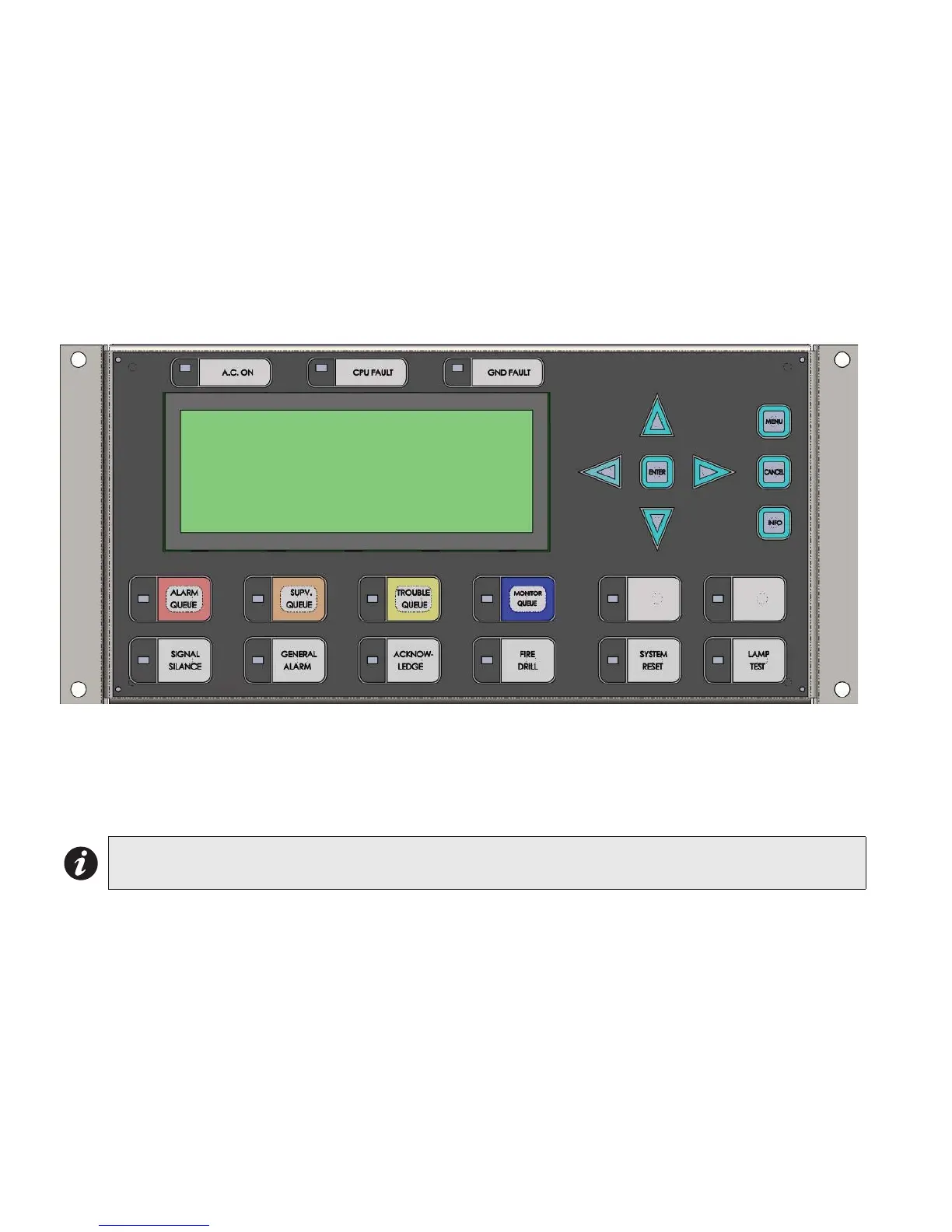
DSPL-420 Main Display Module
The DSPL-420 mounts into backboxes BB-5008(R), BB-5014(R) and BBX-FXMNS. This display is part of the
following main fire alarm chassis: FX-2003-12NDS, FX-2003-12XTDS, FX-2009-12NDS, FX-2017-NDS, and FX-
2000NDS.
Figure 12: DSPL-420 Main Display Module (Part of Main Chassis c/w Main Fire
Alarm Module)
P1: Cable connects to P14 of the FX-2000N main fire alarm board (Figure 11).
P2: Connection to P1 of any adder display module if used.
Note: The main display module comes with slide-in paper labels including both English and French slide-
ins, and laser printer-compatible blanks for zone labelling.