FleX-Net
TM
Installation and Operation Manual
59
Power Supply Connections
The power supply is part of the main chassis. The ratings are outlined in the table below.
See Appendix A for more power supply specifications. Wire as shown below with proper gauge wire.
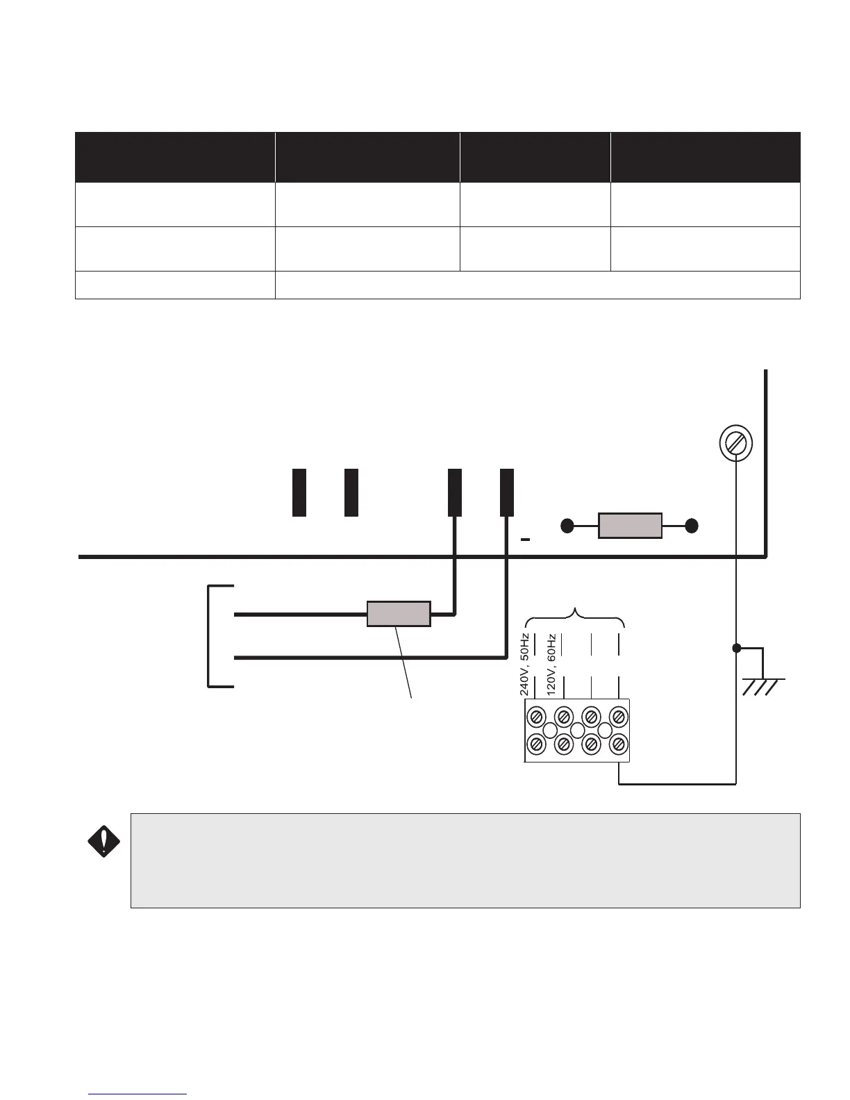
Figure 44: Power Supply Connections
Model Electrical Input Ratings
Power Supply
Total Current
Battery Fuse on Main
Module
FX-2003-12N/DS & FX-2017-
12N/DS Main Chassis
120 VAC, 60 Hz, 2A /
240VAC, 50hz, 1A
12 amps maximum
20 Amp, 1-1/4" Slow Blow
Non-replaceable Fuse
FX-2009-12N/DS Main
Chassis
120 VAC, 60 Hz, 2A /
240VAC, 50hz, 1A
12 amps maximum
20 Amp, 1-1/4" Slow Blow
Non-replaceable Fuse
All Chassis’ IN-LINE 20 Amp, 1 1/4” Fast Acting Fuse, positive side of Battery Connection
CAUTION:
• To prevent sparking, connect batteries after the system’s main A.C. power is turned ON.
• Do not exceed power supply ratings.
• Adhere to voltage markings as specified on labels.
P13
CONNECT GREEN
EARTH GROUND WIRE
TO MAIN MODULE PCB
MOUNTING SCREW.
N
G
GREEN
TO 24 VDC
BATTERY
BLACK
P11
P10
P12
+
BAT
RED
TO DEDICATED
BRANCH CIRCUIT
L
L
20 Amp, 1 1/4” IN-LINE
FAST ACTING FUSE
20 Amp, 1 1/4” SLOW
BLOW FUSE
FUSE
GND