Field Wiring
44
Field Wiring
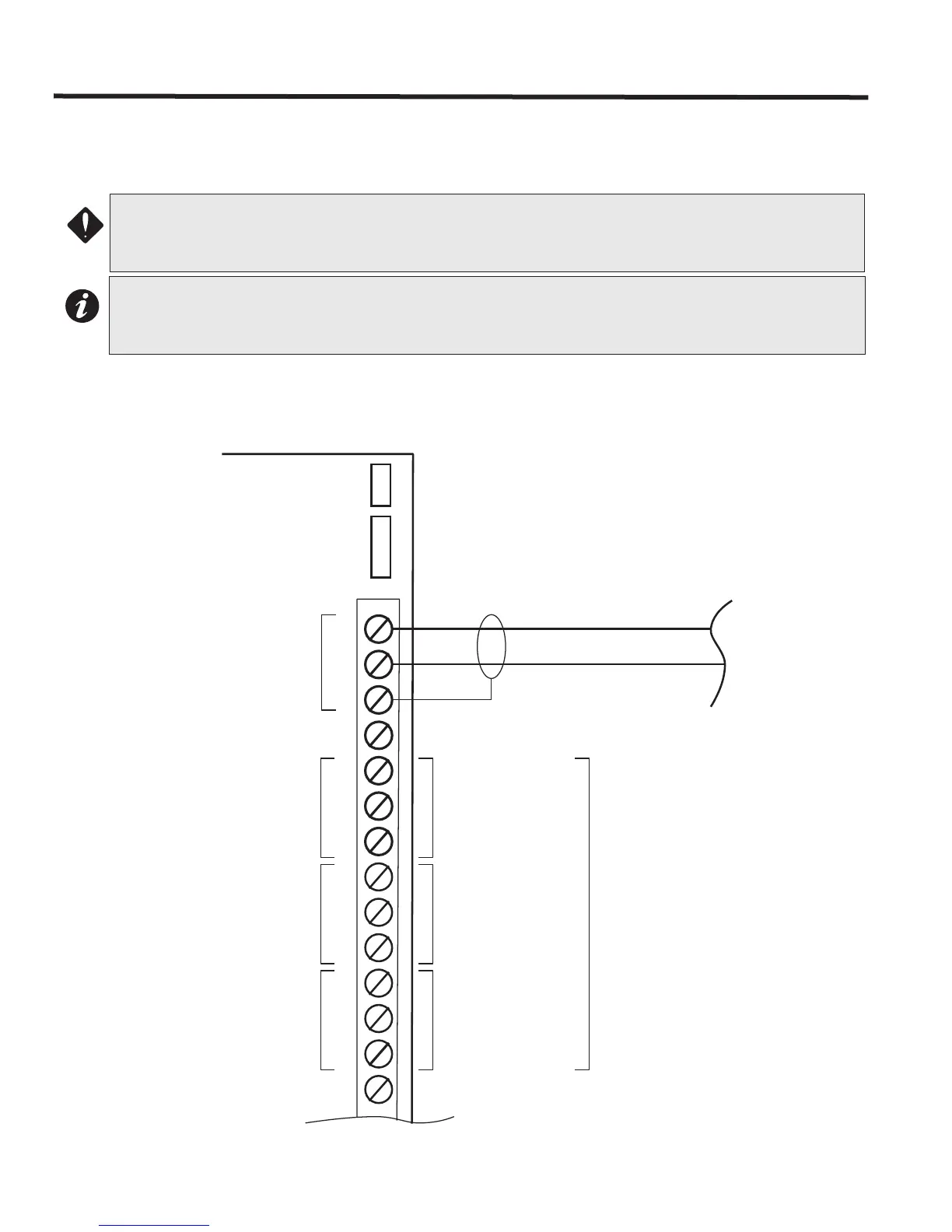
Main Fire Alarm Module Terminal Connections
Wire devices to terminals as shown in below. Refer to Appendix A for specifications and to LT-1023 for compatible
devices.
Figure 29: Main Fire Alarm Controller Board Field Terminal Connections
ATTENTION: Do not exceed power supply ratings:
Main Chassis FX-2003-12N/DS or FX-2017-12N/DS: total current for NACs is 10A max.
Main Chassis FX-2009-12N/DS total current for NACs is 10A max.
Notes:
The terminal blocks are removable for ease of wiring.
All power limited circuits must use type FPL, FPLR, or FPLP power limited cable.
COM
-
RS485
NO
NC
COM
TROUBLE
NO
NC
COM
SIG GND
or COM(-)
NO
NC
ALARM
USE TWISTED SHIELDED PAIR
22 AWG UP TO 2000 FT.
20 AWG UP TO 4000 FT.
SUPV.
+
S
RS-485 INTERFACE TO
ANNUNCIATORS AND
OTHER DEVICES
(POWER LIMITED)
NOT USED
MUST BE
CONNECTED TO A
LISTED POWER
LIMITED SOURCE
OF SUPPLY
COMMON TROUBLE
CONTACTS
24 VDC, 1 AMP
RESISTIVE LOAD
AUXILIARY COMMON
SUPERVISORY
CONTACTS
24 VDC, 1 AMP
RESISTIVE LOAD
AUXILIARY COMMON
ALARM CONTACTS
24 VDC, 1 AMP
RESISTIVE LOAD
S
Shield one end of the
RS-485 LOOP ONLY
FX-2000N Main Fire
Alarm Controller board
P4
P3