Installing and Removing Amplifiers
88
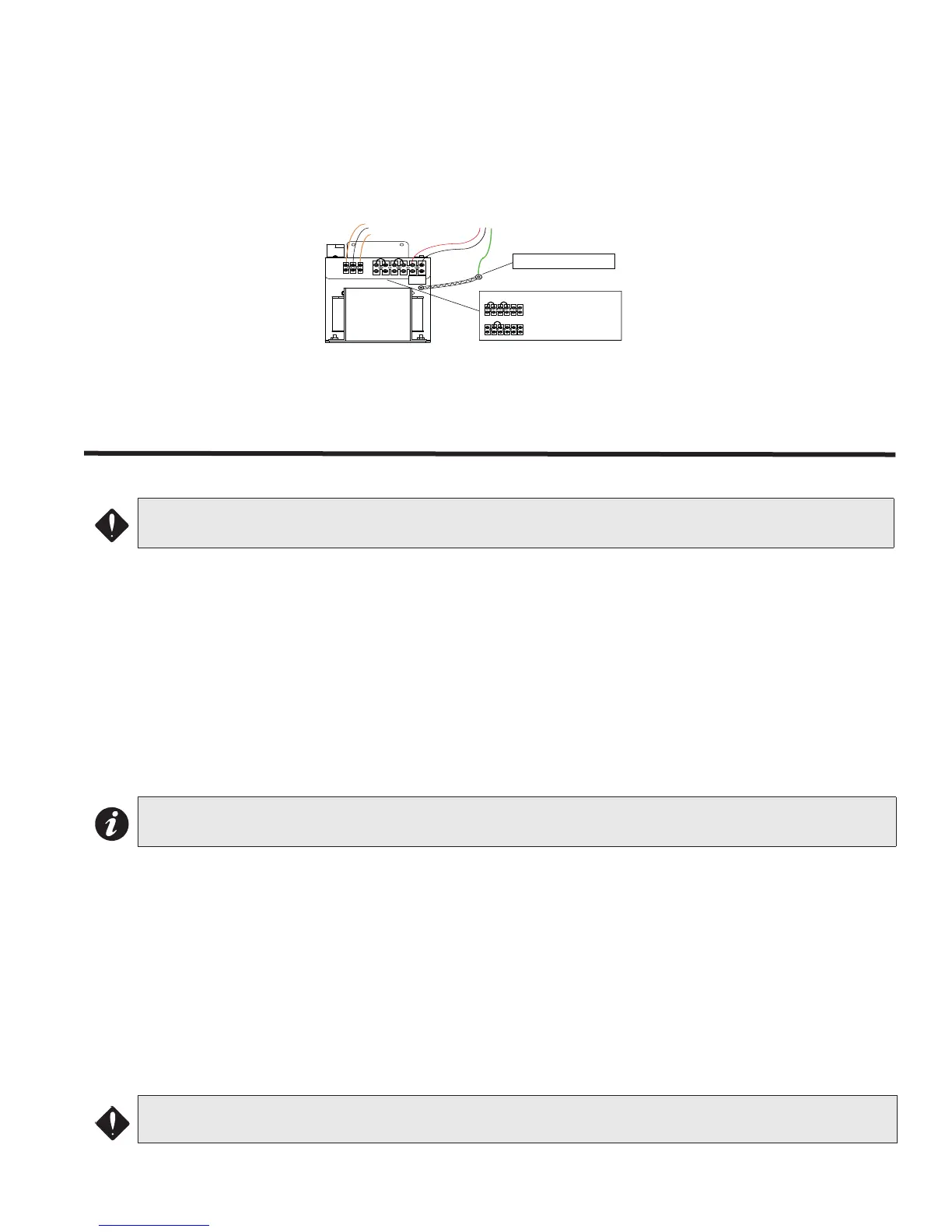
QPS-5000N Power Supply Connection
Two jumpers are provide as shown in figure below for 120 VAC connection. For 240 VAC application, remove both
jumpers and replace one jumper between the two middle terminals. The two terminals on the right are N (neutral),
L (live) for AC voltage connection. The three terminals on the left are connected from the QMB-5000N motherboard
as orange-white-orange (left to right) in that order.
Installing and Removing Amplifiers
Installing QAA Amplifier Modules
1. Hold the amplifier to be installed by the backplate edges. Do not handle, push or pull any of the components on
the amplifier (especially not the transformer) as this will damage those components.
2. Line up the amplifier being installed with the two plastic runners on the card cage and slide the amplifier back
to the point where the amplifier just about touches the pins on the QMB-5000N/B motherboards.
3. Make sure that the amplifier is square with the motherboard.
4. Gently push the amplifier forward to line up the amplifier connector with the motherboard pins. Once you have
a sense of feel that the amplifier connector and the motherboard pins are properly lined up, place one thumb
on the top edge of the backplate and the other thumb on the bottom of the backplate and carefully push the
amplifier in. You should hear a slight thud sound when the amplifier is snapped into place.
Removing the QAA Amplifier Modules
1. Disconnect all cables connected to the amplifier. Do not handle, push or pull any of the components on the
amplifier (especially not the transformer) as this will damage those components.
2. Place the forefinger of one hand on the top inside edge of the front heat sink (the heat sinks are the two long
silver channel-like metal covers opposite the backplate) and the forefinger of the other hand on the bottom
edge of the backplate behind the card cage frame.
3. Carefully pull and rock the amplifier forward until the amplifier connector is disconnected from the motherboard
pins.
4. Holding the amplifier firmly by the backplate edges, slide the amplifier forward and completely remove it from
the card cage.
ATTENTION: Improper installation or excessive force will damage the motherboard and modules being
installed or removed.
Note: If the amplifier connector is not properly lined up with the motherboard pins, or if excessive force is
used, the pins on the motherboard can be damaged.
ATTENTION: Power should be disconnected before removing and inserting modules.
Orange- White-Orange
Wires connected to
QMB-5000B Motherboard
120 VAC or
240 VAC
Live (Black)
Ground
Earth Ground stud in QBB-5001 Backbox
Neutral (White)
Connect AC ground to Earth Ground
stud located in the QBB-5001 Backbox.
L N
L N
L N
QPS-5000N
120 VAC Select
120/240 VAC SELECTION
OR
240 VAC Select
Default Jumper Positions
Discard unused Jumper
Ground Braid