FleX-Net
TM
Installation and Operation Manual
121
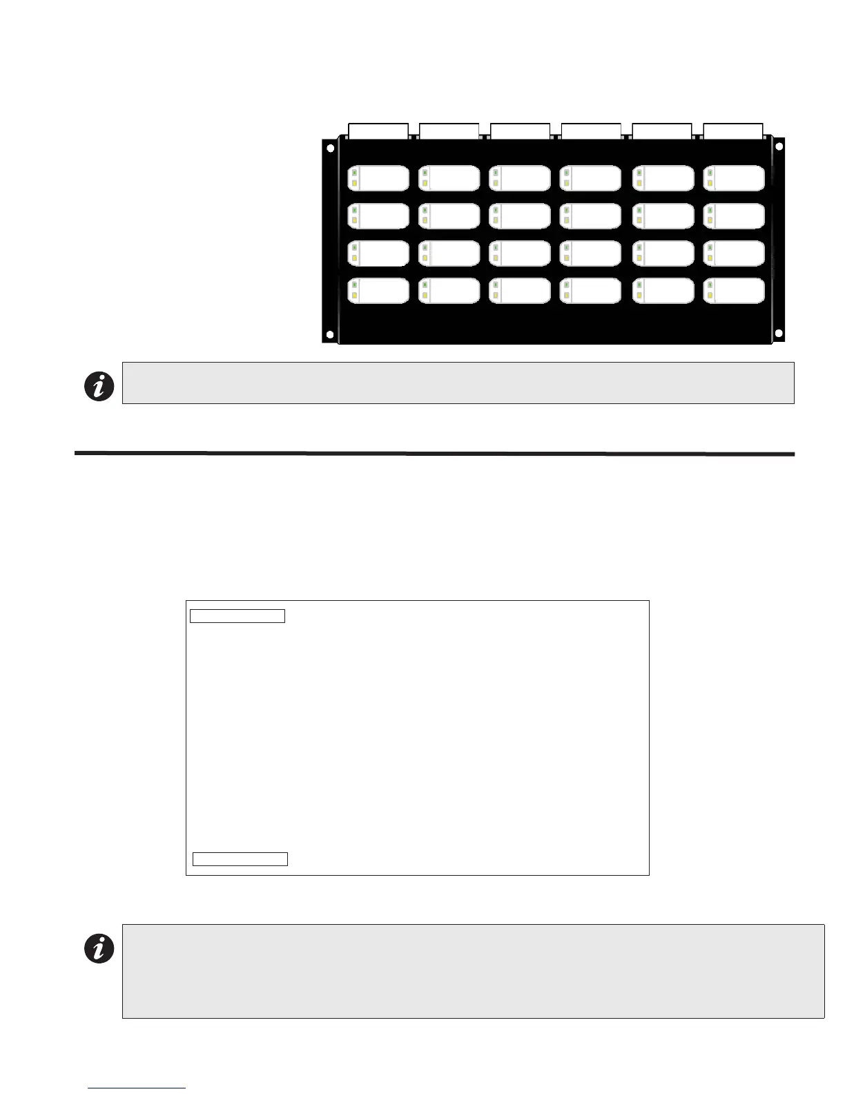
Figure 87: QAZT-5302/DS Network Firefighters' Telephone Selector Panel
Each QAZT-5302/DS
annunciates and controls up to 24
telephone zones. There is one
button and two LEDs per zone.
The lower amber LED indicates
zone trouble. The upper green
LED indicates whether that zone
is selected for telephone
communication.
Press the button to turn the
selection for telephone
communication for that zone ON
and OFF.
QAZT-5302/DS Network Firefighters’ Telephone Selector Panel
Connect the first QAZT-5302 Network Firefighters’ Telephone Selector panel to the master telephone by connecting
P1 cable into P2 on the QMT-5302N Master Telephone. P2 of the QAZT-5302 is connected to P1 of the next display
panel (up to six total).
Figure 88: QAZT-5302 Telephone Selector Board
Note: Use configurator to set up the QAZT-5302/DS Telephone Zone Selector Panels.
Note: All modules such as QMP-5101N/NV Network Master Paging Control Module, the QMT-5302N/NV Network
Master Firefighters’ Telephone Control Module, the IPS-2424/DS display module and the paging or
telephone selector panel QAZT-5302/DS are daisy chained together starting from the FX-2000N LCD
display module, DSPL-420, DSPL-2440, RAXN-LCD or RAXN-LCDG. Total number of boards allowed in the
daisy chain connection is 6 (12 frames).
Telephone
#1
Telephone
#2
Telephone
#3
Telephone
#4
Telephone
#5
Telephone
#6
Telephone
#7
Telephone
#8
Telephone
#9
Telephone
#10
Telephone
#11
Telephone
#12
Telephone
#13
Telephone
#14
Telephone
#15
Telephone
#16
Telephone
#17
Telephone
#18
Telephone
#19
Telephone
#20
Telephone
#21
Telephone
#22
Telephone
#23
Telephone
#24
P2
P1
CONNECTION TO NEXT DISPLAY PANEL
P1 CONNECTS TO P2 OF THE QMT-5302N NETWORK MASTER TELEPHONE CONTROL MODULE
QAZT-5302 ADDRESSABLE
TELEPHONE SELECTOR PANEL