FleX-Net
TM
Installation and Operation Manual
25
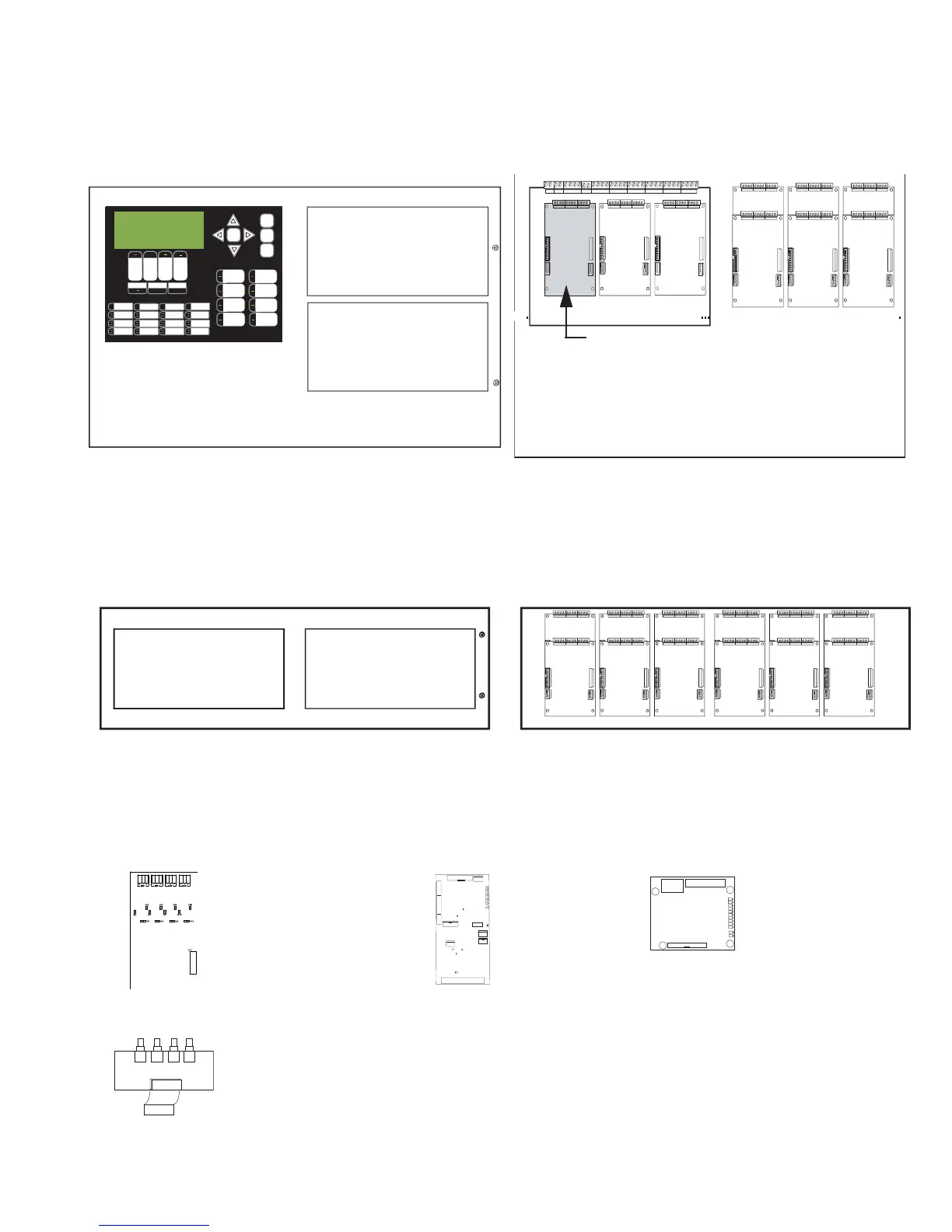
FX-2009-12N Large Main Chassis
Mounts and occupies four display positions in BB-5008 or BB-5014 Enclosures, and supports two display modules and
nine adder modules. This large chassis size can hold the integrated audio and/or telephone modules.
ECX-0012 Expander Chassis for FX-2009-12N
Mounts and occupies two display positions in BB-5008 or BB-5014 Enclosures, and supports two display and 12 adder
modules.
NETWORK CONTROLLER MODULES
The FNC-2000 Fire Network Controller module is mounted in position 2 over the FX-2000N main board. The TNC-
5000 Telephone Network Controller module is mounted over the ANC-5000 Audio Network Controller module and
both are mounted on a metal plate and that plate is mounted in a BB-5008 or BB-5014 backbox in positions marked
4 to 9 inclusive, refer to previous drawing of large chassis.
Exterior View Interior View
Exterior View Interior View
FNC-2000
Fire Network Controller
Module
FOM-2000-SP
Fiber Optics Module
Mounts over the
FNC-2000 Fire Network
Controller Module
ANC-5000
Audio Network
Controller
Module
TNC-5000
Telephone
Network
Controller
Module
ALARM
QUEUE
SUPV.
QUEUE
TROUBLE
QUEUE
MONITOR
QUEUE
A.C. ON
CPU FAULT
GND FAULT
SIGNAL
SILENCE
GENERAL
ALARM
ACKNOW-
LEDGE
FIRE
DRILL
SYSTEM
RESET
LAMP
TEST
ENTER
MENU
CANCEL
INFO
LED 0
LED 1
LED 2
LED 3
LED 4
LED 5
LED 6
LED 7
LED 8
LED 9
LED 10
LED 11
LED 12
LED 13
LED 14
LED 15
CONFIGURABLE
SWITCH/LED 3
CONFIGURABLE
SWITCH/LED 7
Mircom FX-2000N
Fire Alarm Control Panel
Normal Condition
December 31, 2009
Cutout to mount
display module
Cutout to mount
display module
4
231
56
789
FX-2000 Main Board
FX-2000N Main Board
Slot 3 is reserved for PR-300 or UDACT-300A. If
not required, this slot can be used to mount any of
the adder modules.
The recommended mounting position is 2 for the
FNC-2000. The FOM-2000-SP board, if used, is
mounted over the FNC-2000 board. Positions 4 to
9 are replaced with the audio and telephone
boards if used.
Cutout to mount
display module
Cutout to mount
display module
*7
*7
*7
*7
*7
*7
*7
*7
*0
0
*0
*0
0.ETWORK23
023
*7
0
023$EBUG
0!-03)NTERFACE
0(?3PEED!UDIO
0