FX-2000 Series Installation and Operation Manual
13
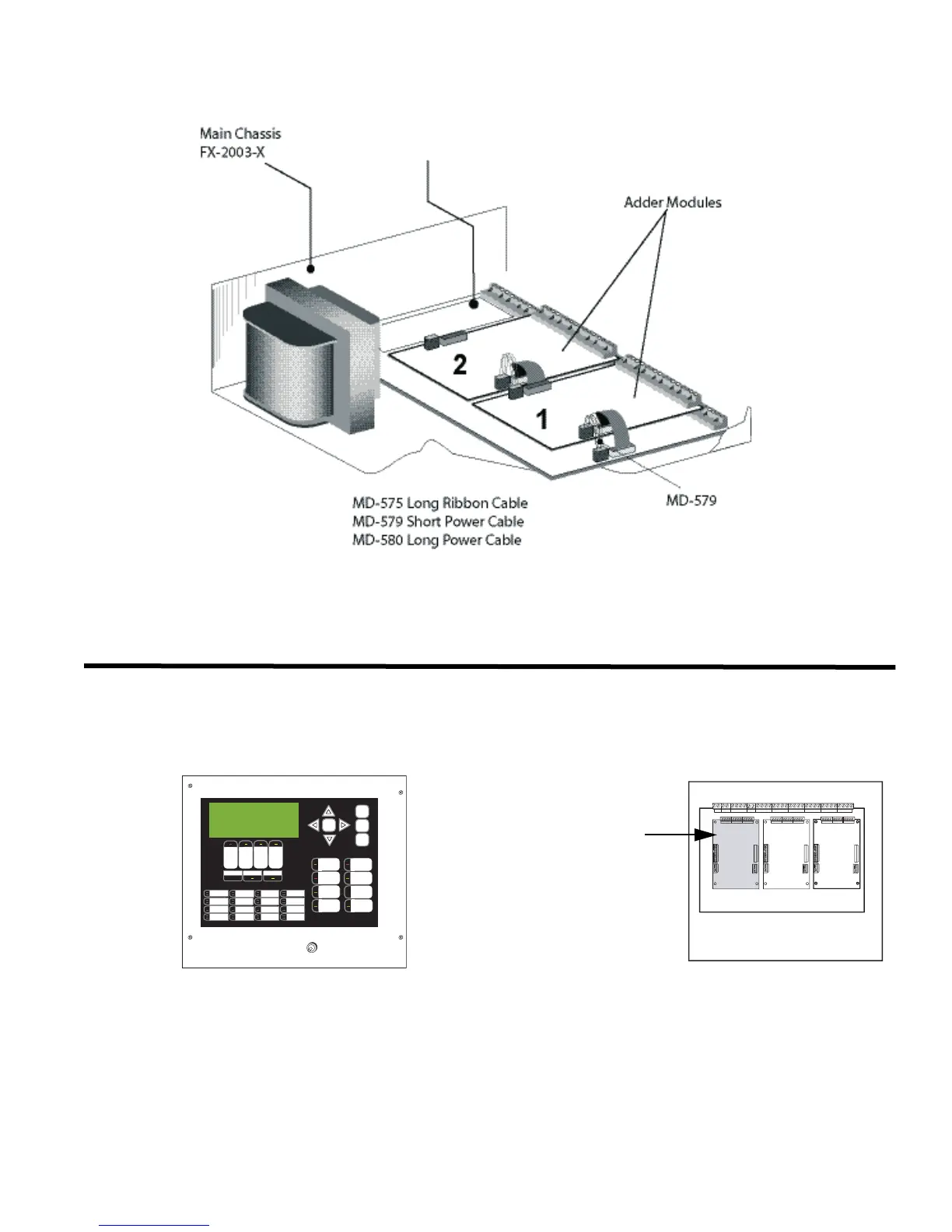
Figure 8: Module Mounting Locations View #2
Display and Adder Modules Mounting Locations
FX-2003-6/FX-2003-12 Compact Main Chassis
Mounts in the BBX-1024 Enclosure and supports three adder modules.
Exterior View Interior View
Provision for PR-300 or UDACT-300A
ALARM
QUEUE
SUPV.
QUEUE
TROUBLE
QUEUE
MONITOR
QUEUE
A.C. ON
CPU FAULT
GND FAULT
SIGNAL
SILENCE
GENERAL
ALARM
ACKNOW-
LEDGE
FIRE
DRILL
SYSTEM
RESET
LAMP
TEST
ENTER
MENU
CANCEL
INFO
LED 0
LED 1
LED 2
LED 3
LED 4
LED 5
LED 6
LED 7
LED 8
LED 9
LED 10
LED 11
LED 12
LED 13
LED 14
LED 15
CONFIGURABLE
SWITCH/LED 3
CONFIGURABLE
SWITCH/LED 7
Mircom FX-2000
Fire Alarm Control Panel
Normal Condition
April 25, 2003
AC LINE
CIRCUIT
BREAKER
FX-2000 Main Board
123
Slot is reserved for
PR-300 or UDACT-
300A. If not
required, this slot
can be used to
mount any of the
adder modules.