EasyManuals Logo

Mircom FX-2000 User Manual

Mircom FX-2000
88 pages
To Next Page IconTo Next Page
To Previous Page IconTo Previous Page
Page #51 background imageLoading...
Page #51 background image
FX-2000 Series Installation and Operation Manual
45
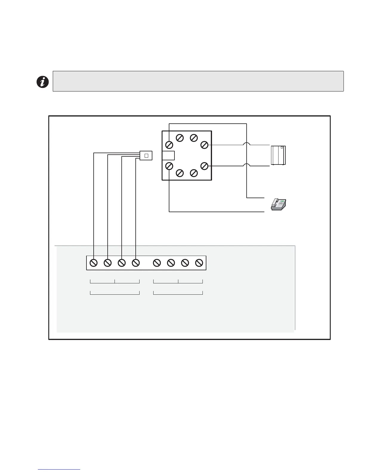
UDACT-300A Main Board Terminal Connections
Wire the two telephone lines to RJ31X Connector terminals as shown in Figure 38 below. The UDACT-300A
terminals are located on the top left hand corner of the board. If using a cellular or wireless service, use the Line 2
interface connection only.
Figure 37: Telephone Line Wiring Diagram
Note: Most Authorities Having Jurisdiction (AHJ) do not allow the connection of premise
telephones. see specifications for more information.
7755
SUHPLVHWHOHSKRQH
,)SHUPLWWHG
7755
/,1( /,1(


3XEOLFVZLWFK
7HOHSKRQHFRPSDQ\
ZLULQJ
7,3
5,1*
7,3
5,1*
5-;
5('
*5((1
*5(<
%52:1
5(6 5(6&2 &2
/LQHLV:LUHGDVVKRZQIRU/LQH
8'$&7$

Table of Contents

Questions and Answers:

Question and Answer IconNeed help?

Do you have a question about the Mircom FX-2000 and is the answer not in the manual?

Mircom FX-2000 Specifications

General IconGeneral
TypeFire Alarm Control Panel
Maximum devices per loop99
Power Supply120 VAC, 60 Hz
Battery Backup24VDC, 7Ah
ProgrammingVia PC
SLC Loops1
Operating Temperature0°C to 49°C (32°F to 120°F)
CompatibilityMircom devices
DisplayLCD

Related product manuals