Appendix C: Power Supply and Battery Calculations
70
Appendix C: Power Supply and Battery Calculations
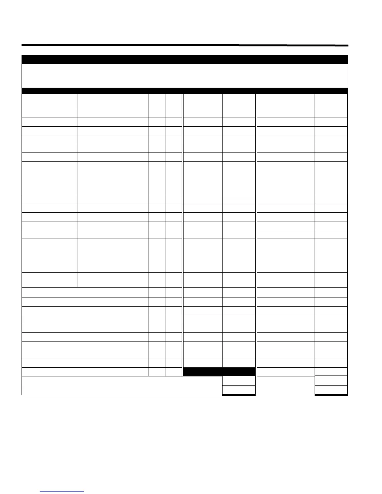
Total Current Requirement: ALARM (B)______ Amps.
Battery Capacity Requirement: ([STANDBY (A) ______ ] X [(24 or 60 Hours) ___ ]) + ([ALARM (B) ______ ] X [
♣
Alarm in Hr.] _____) = (C) ______AH
Main Chassis Selection: Select MCC-1024-6(S) if (B) is less than 12 Amps.
Battery Selection: Multiply (C) by 1.20 to derate battery.
Batteries:BA-110(10AH), BA-117(17AH) will fit in the BBX-1024
BA-124 (24AH) will fit in the BBX-1072A, BB-5008, or the BB-5014
BA-140(40AH) will fit in the BC-1160 battery cabinet
* Assuming three initiating circuits in alarm.
♣
Use 0.084 for five minutes of alarm or 0.5 for thirty minutes of alarm as a multiplier figure.
♦
Using the MIR-425/U 2-wire smoke detector. See Appendix B: Compatible Devices on page 61 for other available smoke detectors.
IMPORTANT NOTICE
The main AC branch circuit connection for Fire Alarm Control Unit must provide a dedicated continuous power without provision of any disconnect
devices. Use #12 AWG wire with 600-volt insulation and proper over-current circuit protection that complies with the local codes. Refer to
Appendix A: Specifications on page 59 for specifications.
Power Requirements (All currents are in amperes)
Model Number Description Qty Standby
Total
Standby
Alarm
Total
Alarm
FX-2003-6/12 Main Chassis (6A/12A) X 0.230 = 0.380 =
FX-2017-12A Main Chassis (12 amp) X 0.230 = 0.380 =
FX-2009-12 Large Main Chassis (12A) X 0.230 = 0.380 =
ALC-198S Single Analog Loop X 0.050 = 0.060 =
ALC-396S Double Analog Loop X 0.050 = 0.060 =
ALC-H16 Adder Controller X 0.035 = 0.050 =
DM-1008A 8 initiating circuit Module X 0.080 =
1 zone active: 0.125
2 zone active: 0.170
4 zone active: 0.275
6 zone active: 0.370
8 zone active: 0.465
=
SGM-1004A 4 indicating circuit Module X 0.060 = 0.258 =
RM-1008A 8 Relay circuit Module X 0.025 = 0.150 =
FDX-008/KI Fan Damper Control Module X 0.015 = 0.035 =
UDACT-300A Dialer Module X 0.045 = 0.120 =
PR-300 City Tie Module X 0.035 = 0.300 =
RAX-1048(TZ) Adder Annunciator Chassis X 0.022 =
1 zone active: 0.026
2 zone active: 0.030
3 zone active: 0.035
4 zone active: 0.039
48 zone active: 0.262
=
IPS-2424
Programmable Input
Switches Module
X 0.010 = 0.015 =
Two-Wire Smoke Detectors X
♦
0.0001
= * 0.090 = 0.090
MIX-1551A Analog Ion Smoke Detector X 200µA = 0.0065 =
MIX-2251/A Analog Photo Smoke Detector X 230µA = 0.0065 =
MIX-5551A/RA Analog Thermal Sensor X 200µA = 0.007 =
MIX-M500MA/MB, MIX-M501MA/MB Monitor X 400µA = 0.0051/0.0055 =
M500CH/A Addressable Control Module X 300µA = 0.0051 =
M500X Fault Isolator Module X 450µA = 450µA =
B524IA Analog Base with Isolator X 450µA = 0.005 =
Four-Wire Smoke Detectors X = =
Signal Load (bells, horns, strobes, and etc.) X
=
Auxiliary Power Supply for Remote Annunciators =
Alarm
=
Total currents (Add above currents) STANDBY (A)(B)