FX-2000 Series Installation and Operation Manual
39
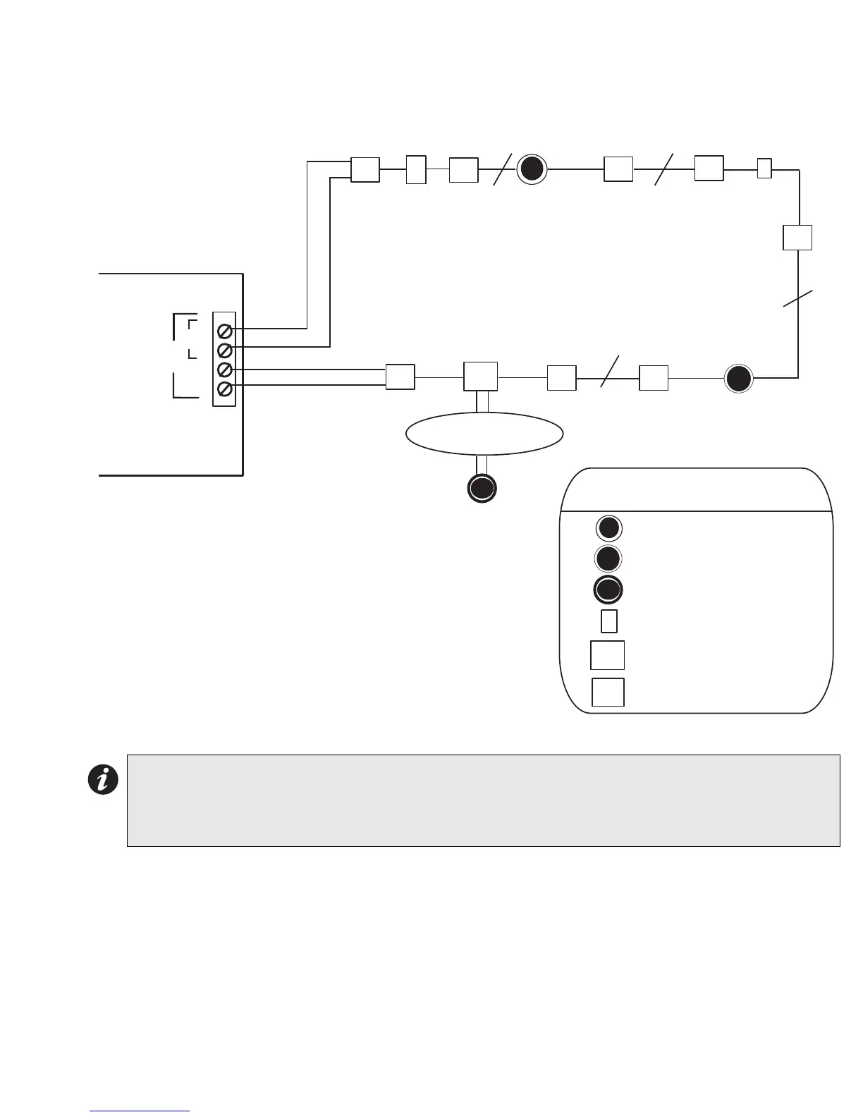
Figure 31: Single Loop Terminal Connections - Style 7
Notes:
• All power limited circuits must use type FPL, FPLR, or FPLP power limited cable.
• Isolators need to be close nipple connected to the device being protected.
• Loop wiring: maximum loop resistance is 40 ohms total. These lines are fully supervised.
LEGEND
Addressable Smoke
Sensor with Isolator Base
Addressable Thermal
Sensor with Isolator Base
Conventional Smoke Sensor
Addressable Manual Pull Station
Fault Isolator Module
Conventional Heat Sensors
and Manual Pull Stations
F
C
s
F
ADDRESSABLE
THERMAL SENSOR
WITH ISOLATOR
BASE
ADDRESSABLE
SMOKE DETECTOR
WITH ISOLATOR
BASE
F
C
s
Addressable Monitor Module
H
S
S
H
TWO WIRES
TWO WIRES
TWO WIRES
I
I
I
I
I
I
I
I
M
M
I
B
A
NALOG
OOP A
+
-
+
-
ALC-198S SINGLE
LOOP MODULE
STYLE 7: For Style 7 operation use isolator
bases for the detectors and use isolator modules
(front and back as shown in this diagram) for the
addressable pull stations, monitor modules, and
control modules