Module Settings
20
Fan Damper Operation
The FDX-008 Fan Damper Control Display module has eight configurable output circuits, each with a three position
switch. The FDX-008KI operates in the same manner as the FDX-008 except zone 8 is controlled by a remote
keyswitch. Each switch has an ON and OFF position, plus an AUTO position. If the switch is placed in the AUTO
position, the output will activate as programmed or configured. The output can be manually turned ON or OFF by
placing the switch in the ON or OFF position, respectively.
Basically each switch can be configured to operate multiple fans or dampers. For each switch, there are 3
operations provided; outputs to turn ON, same outputs to turn OFF and inputs to bypass.
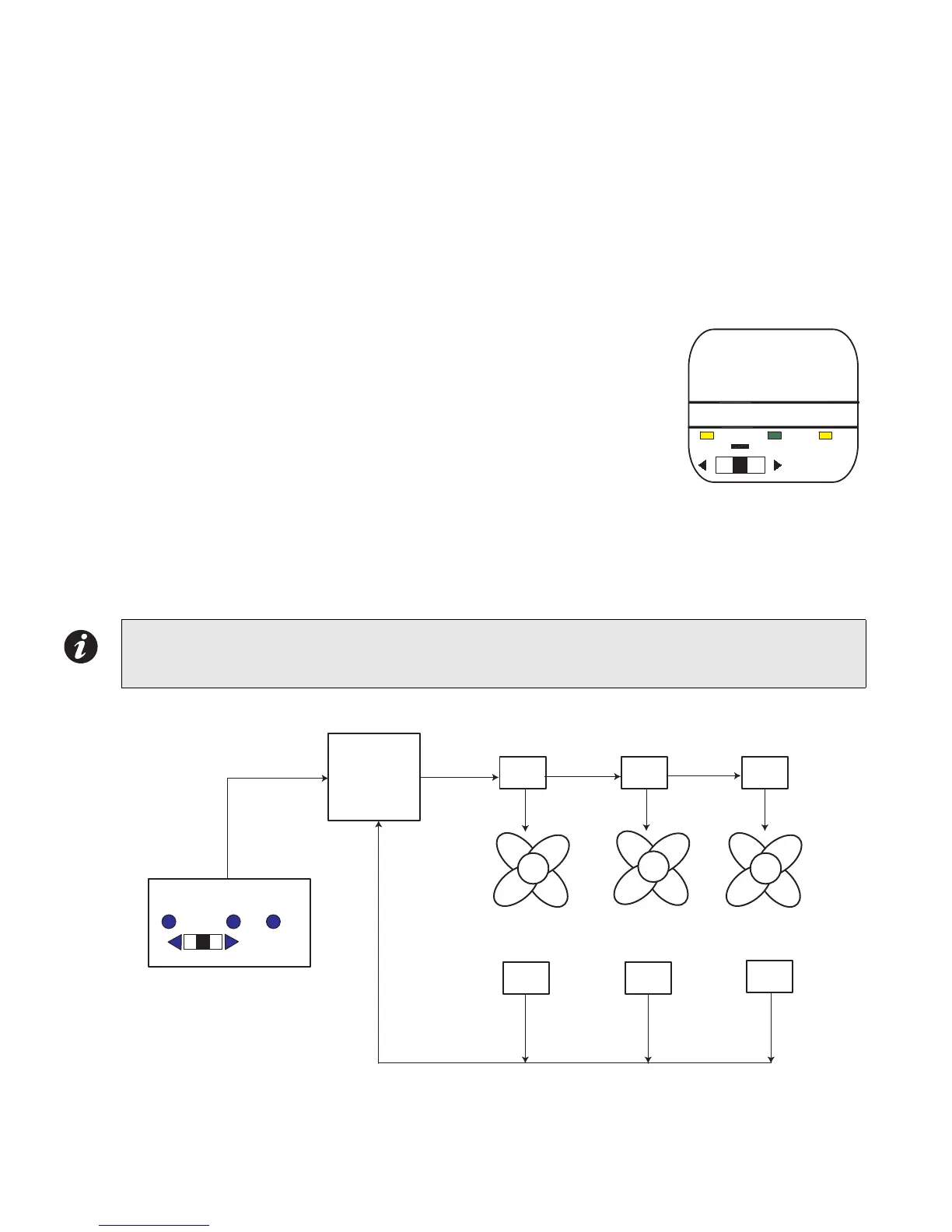
An example of the most common use of the FDX-008 or FDX-008KI Fan Damper Control Display module is to
operate exhaust fans and confirm fan operation (via monitor modules). See FDX-008 Block Diagram on the next
page for a block diagram of fan and monitor set up.
Example
As shown in the figure to the right, Parking Garage #1 has 3 exhaust fans. The three
position switch is configured to operate (to turn ON) fans 1, 2 and 3 in stairwell #1. The
switch is set in the AUTO position. Upon activation (via alarm or some other
programmed trigger) with the switch in AUTO, the 3 fans (1,2, and 3) in stairwell #1 are
turned ON automatically. Monitor modules in the Parking Garage #1 detect that all 3
fans are operating, therefore the ON LED will illuminate steadily. If one of the fans did
not turn ON (due to malfunction), the ON LED will flash. The TRBL (trouble) LED will
illuminate steady amber based on feedback from the monitor module that one or more
of the fans is not working.
ON LED shows steady for all outputs operating and confirmed.
OFF LED shows steady for all outputs NOT operating and confirmed.
TRBL LED shows steady for one or more outputs NOT operating and confirmed.
Figure 15: FDX-008 Block Diagram of Fan and Monitor Setup
Note: A bypass function always has priority, so that if a circuit is bypassed by moving the switch manually
or by loop bypass (FX-2000 Fire Alarm Panel), no other action will operate this switch other then
again moving the switch manually or by un-bypassing the loop.
OFF AUTO ON TROUBLE
PARKING GARAGE #1,
FANS 1, 2 , 3
OFF AUTO ON TROUBLE
FX-2000 FIRE
ALARM PANEL
FANS
OUTPUT MODULES
MONITOR MODULES
FDX-008/KI FAN/DAMPER CONTROL MODULE