Module Settings
30
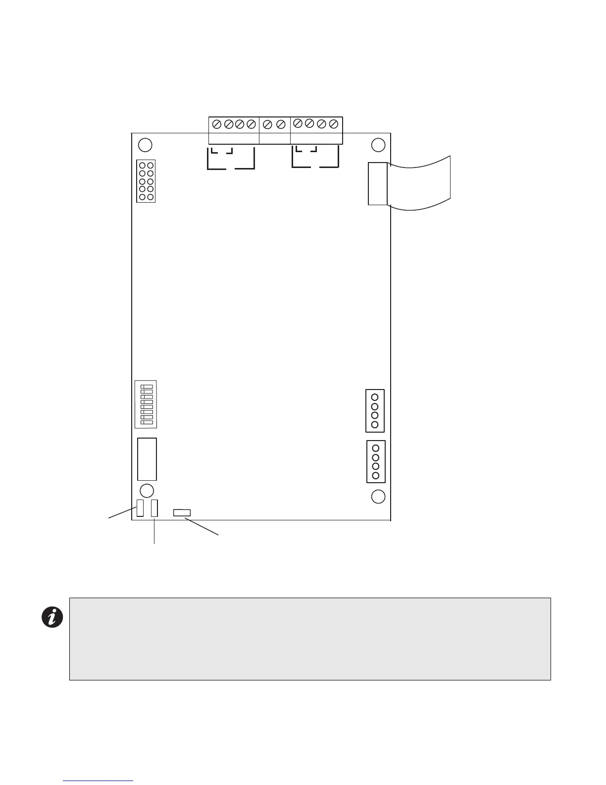
Figure 23: ALC-396S Dual Intelligent Analog Loop Controller Module
Mount the ALC-396S Dual Intelligent Analog Loop Controller module as shown in on page 13. The module may be
mounted over the main chassis board or in any position that an adder module is mounted.
Wiring The Addressable Loops
There are two addressable loops present on this board (ALC-396S) that are wired in the same manner
as shown in the wiring diagrams beginning with Main Fire Alarm Module Terminal Connections on
page 33. Although these drawings show only Loop 1, Loop 2 is wired in the same way as Loop 1 is. Note
that Loop 1 and Loop 2 do not have to be wired in the same class, such as Class A or Class B or Style 7.
Therefore Loop 1 may be wired as Class A and Loop 2 may be wired as Class B.
1
8
RS-485
CABLE
RS-485
ADDRESS
DIP
SWITCH
BDM
PORT
JW2 - THE
JUMPER IS
KEPT HERE
FOR
NORMAL
OPERATION
JW1 - PINS ARE
SHORTED
MOMENTARILY TO
RESET
HARDWARE
JW3 - JUMPER
FROM JW2 IS
PLACED HERE TO
BYPASS
WATCHDOG FOR
FACTORY
DOWNLOADING
USING BDM
POWER
CABLE
POWER
CABLE
LOOP A
DIP SWITCHES ARE FOR
THIS BOARD=S ADDRESS.
SW-1 IS THE LEAST
SIGNIFICANT DIGIT (BINARY).
ACTIVE POSITION IS OFF.
+ - + -
B
A
P3
P2
P1
P5
P4
LOOP B
+ - + -
B
A
SHIELD