Field Wiring
46
Power Supply Connections
The power supply is part of the main chassis. The ratings are outlined in the table below.
See Appendix A: Specifications on page 59 for specifications. Wire as shown below in Figure 39 using proper wire
gauges.
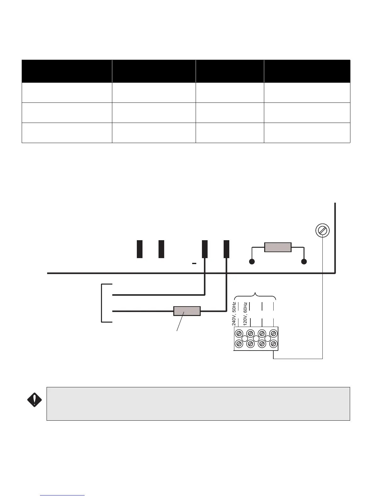
Figure 38: Power Supply Connections
Model Electrical Input Ratings
Power Supply
Total Current
Battery Fuse on Main
Module
FX-2003-6 Main Chassis
120 VAC, 60 Hz, 2A /
240VAC, 50hz, 1A
6 amps maximum
Replace with 20 Amp, 1-1/
4" Fuse
FX-2003-12 & FX-201712A
Main Chassis
120 VAC, 60 Hz, 2A /
240VAC, 50hz, 1A
12 amps maximum
Replace with 20 Amp, 1-1/
4" Fuse
FX-2009-12 Main Chassis
120 VAC, 60 Hz, 2A /
240VAC, 50hz, 1A
12 amps maximum
Replace with 20 Amp, 1-1/
4" Fuse
CAUTION:
• To prevent sparking, connect batteries after the system’s main A.C. power is turned ON.
• Do not exceed power supply ratings.
P13
CONNECT GREEN
EARTH GROUND WIRE
TO MAIN MODULE PCB
MOUNTING SCREW.
N
G
GREEN
TO 24 VDC
BATTERY
BLACK
P11
P10
P12
+
BAT
RED
TO DEDICATED
BRANCH CIRCUIT
L
L
20 Amp
FAST ACTING FUSE
FUSE