Chapter 9
156
Logic programming – Function blocks
Ensure that the transitions of the signals for resetting fulfill the requirements!
In case of a short-circuit to High (to 24 V DC) at a physical input, the evaluated signal
can have a pulse when the signal is reset due to the short-circuit detection. If such a
pulse can result in a dangerous state in the machine, the following points have to be
observed:
Ensure protected cable laying for the signal line (due to cross-circuiting to other
signal lines).
No short-circuit detection, i.e. do not reference to test outputs.
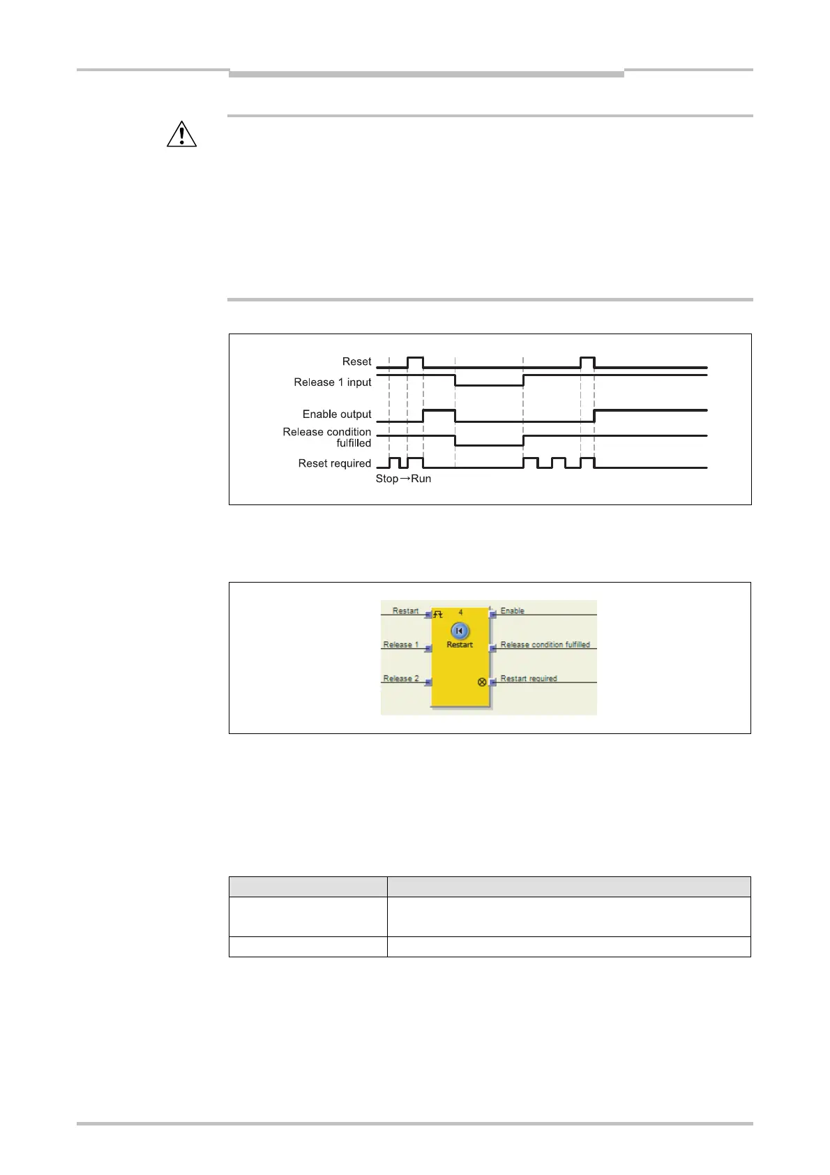
Sequence/timing diagram
9.8.2 Restart
Function block diagram
General description
The internal logic of the Restart function block has the same functionality as the Reset
function block. The Restart function block allows graphic differentiation between the
function blocks with regard to the observation of application standards for
acknowledging a manual restart request.
Parameters of the function block
Parameter Possible values
Min. restart pulse time 100 ms
350 ms
Number of inputs 2 to 8 (= 1 to 7 Release inputs activated)
Release condition fulfilled output
The Release condition fulfilled output displays the result of an AND combination of
all activated Release inputs. It is High if all activated Release inputs are High.
ATTENTION
Figure 133:
Sequence/timing diagram
for the Reset function block
Figure 134:
Function block diagram for
the Restart function block
Table 64:
Parameters of the Restart
function block

 Loading...


