Chapter 5
58
The graphical user interface
The input and output status for the WS0-XTIO and WS0-XTDI modules is available
only with firmware version V2.00 and higher.
5.6.7 CPU markers
CPU markers are available as inputs and outputs in the Logic editor. They can be
used e.g. for the creation of logic loop backs or to connect an output of a function
block that is placed on one page of the logic editor to an input of a function block on
another page of the logic editor.
A CPU marker consists of an output marker and an input marker. The input marker
always takes the same value (High or Low) as the corresponding output marker with a
delay of one logic execution time.
Take the delay caused by CPU markers into account!
CPU markers always cause a delay of one logic execution time, because the input
marker always uses the value of the output marker in the previous logic cycle. The
resulting delay must be considered for the response time calculation and for the
functionality.
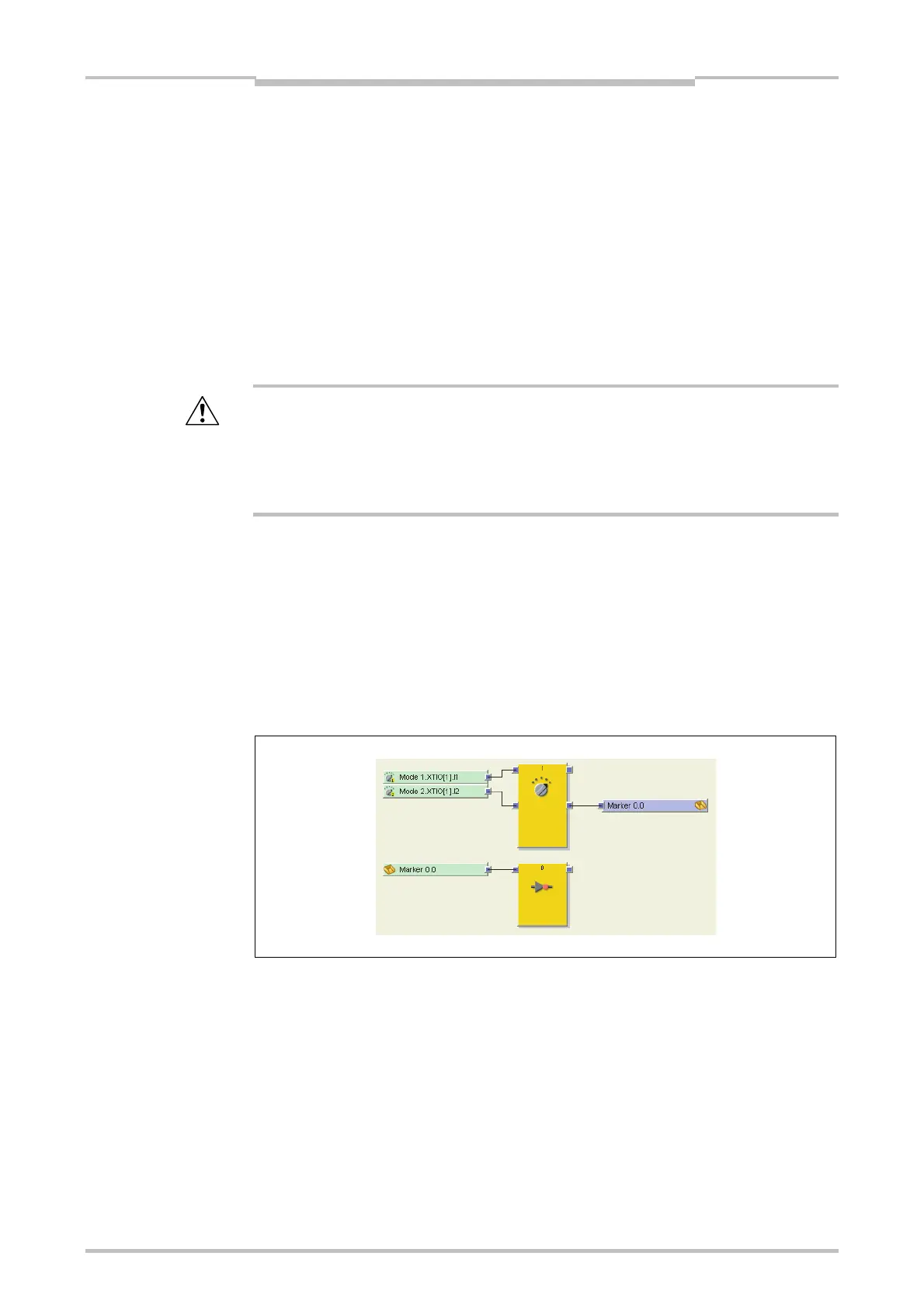
How to use a CPU marker:
Connect a CPU output marker (e.g. Marker 0.0) from the Outputs tab of the logic
editor to the function block output that you want to use. Each CPU output marker
can be used only once in a project.
Connect the corresponding CPU input marker (e.g. Marker 0.0) from the Inputs tab
of the logic editor to the function block input where you want to use the signal from
the first function block as shown in the following screenshot. CPU input markers
can be used several times in a project.
Note
ATTENTION
Figure 28:
Example for the usage of a
CPU marker

 Loading...


