Chapter 12
279
Device states of the MELSEC-WS safety controller
12 Device states of the MELSEC-WS safety controller
The MELSEC-WS safety controller knows different device states during operation.
Some device states require a user intervention, e.g. the state transition from Stop to
Run or vice versa using the Setting and Monitoring Tool. Other states are based on
the internal self-test of the safety controller, e.g. Internal error. The following table
summarizes the device states of the safety controller.
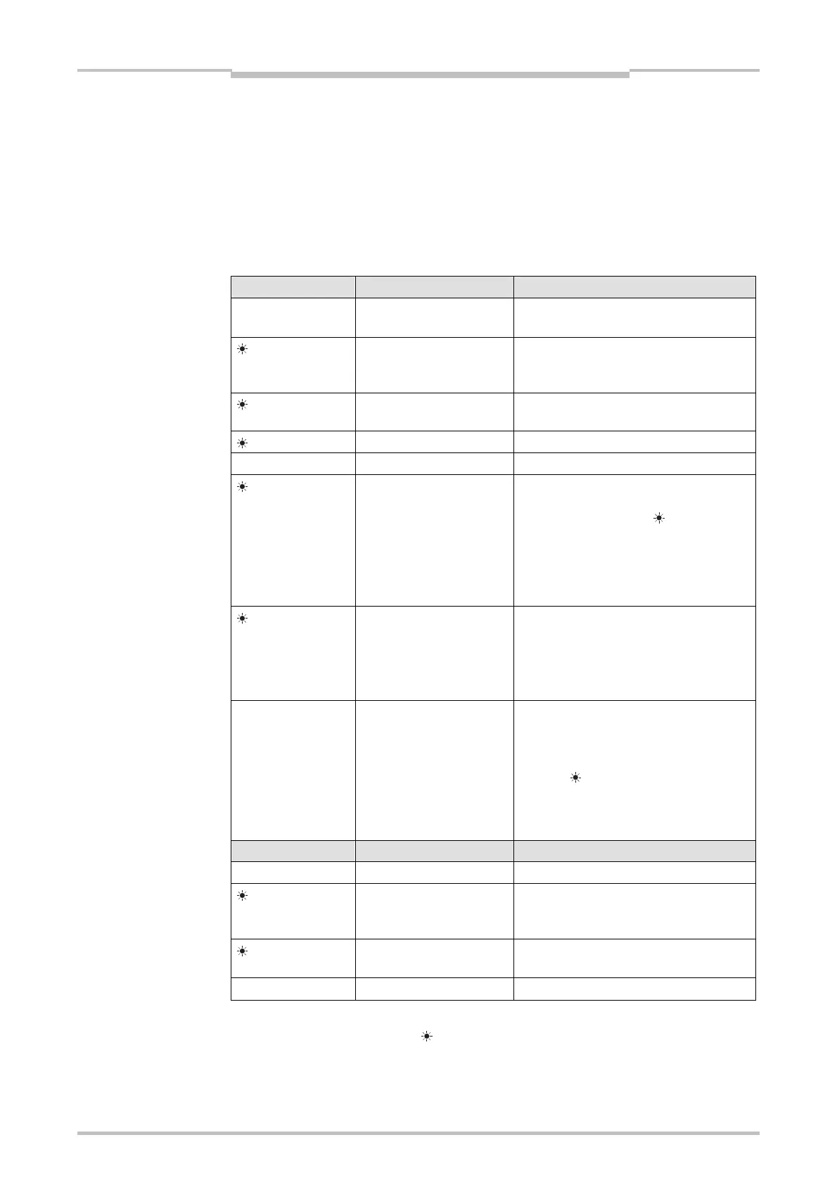
MS LED Meaning Notes
Supply voltage is outside
range
Switch on the supply voltage and check it
at the terminals A1 and A2.
Red/Green (1
Hz)
A self test is being carried
out or the system is being
initialized
Please wait …
Green (1 Hz)
System is in Stop state Start the application in the Setting and
Monitoring Tool.
Green (2 Hz)
Identify (e.g. for Flexi Link) –
Green
System is in Run state –
Red (1 Hz)
Invalid configuration Check the module type and version of the
CPU module and safety I/O modules
whose MS LED flashes
Red/Green.
If appropriate, adapt the configuration
using the Setting and Monitoring Tool.
For detailed diagnostics information refer
to the Setting and Monitoring Tool.
Red (2 Hz)
Critical error in the system,
possibly in this module.
Application is stopped. All
outputs are switched off.
Switch the supply voltage off and on
again. If the error is not eliminated after
multiple repetition, replace this module.
For detailed diagnostics information refer
to the Setting and Monitoring Tool.
Red
Critical error in the system,
possibly in another
module. Application is
stopped. All outputs are
switched off.
Switch the supply voltage off and on
again.
If the error is not eliminated after multiple
repetition, replace the module which
displays
Red (2 Hz). If this is not the
case, use the diagnostic functions of the
Setting and Monitoring Tool to narrow
down the respective module.
CV LED Meaning Notes
Configuration in progress Please wait …
Yellow (2 Hz)
Storing of configuration
data in the memory plug
(non-volatile memory)
Supply voltage may not be interrupted
until the storage process has been
completed.
Yellow (1 Hz)
Unverified configuration Verify configuration with the Setting and
Monitoring Tool.
Yellow
Verified configuration –
Symbol description:
: LED off, : LED lights up,
: LED flashes
Table 115:
Device status and LED
displays on the CPU module

 Loading...


