Chapter 9
190
Logic programming – Function blocks
If signals from tested sensors are connected to WS0-XTDI or WS0-XTIO modules,
the discrepancy time should be at least the set Test gap (ms) plus the Max. off-on
delay (ms), because a signal change at the module input can be delayed for this
time. Both values are displayed in the Setting and Monitoring Tool report for the
used test output.
If both inputs of a pair are connected to the same input signal, the evaluation
corresponds to the single-channel evaluation, i.e. no equivalence check or
antivalence check and no discrepancy time monitoring is carried out.
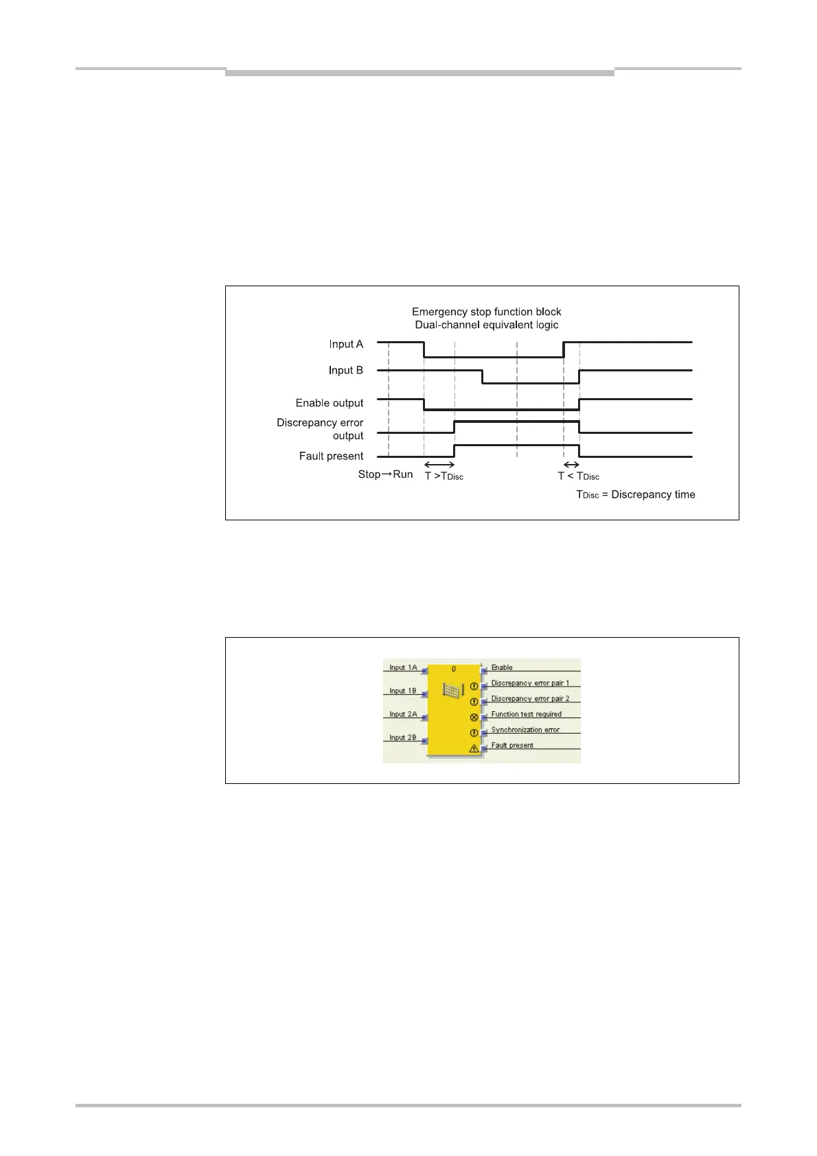
Sequence/timing diagram
9.9.3 Double dual-channel evaluation (2 pair synchronization evaluation)
and synchronization time
This section relates to the Safety gate monitoring and Two hand control type IIIC
function blocks.
The double dual-channel evaluation (synchronization evaluation) evaluates the correct
sequence of the two input signals for each of the two input pairs as described in
Section 9.9.2. Additionally the correct sequence of the two dual-channel evaluations in
relation to each other is monitored. It is expected that if one of the two dual-channel
evaluations has caused a switching off, the other dual-channel evaluation will follow
accordingly.
An optional synchronization time can be defined. The synchronization time defines for
how long the two dual-channel evaluations may have not synchronous states without
this being considered as an error.
The synchronization time differs from the discrepancy time: It evaluates the relation
between the two dual-channel evaluations while the discrepancy time applies to an
input pair of one dual-channel evaluation.
Figure 176:
Sequence/timing diagram
for the Emergency stop
function block
Note
Figure 177:
Double dual-channel
evaluation with the Safety
gate monitoring function
block

 Loading...


