Chapter 9
196
Logic programming – Function blocks
Function test
In some applications, safeguarding devices require cyclic physical testing in order to
verify that the device continues to operate properly.
If the Safety gate monitoring function block is configured with the Function test
required parameter, the input signal(s) must change once per machine cycle in a way
that no enable condition exists anymore and back (e.g. as a result of opening and
closing of a safety gate).
Typically the Function test request input is connected to the machine cycle contact.
If according to the configuration a function test is required, this has to be performed
under the following conditions:
after the MELSEC-WS safety controller has changed from the Stop state to the Run
state, and
after each rising edge (Low to High) at the Function test request input.
This is indicated by a High signal at the Function test required output. The Function
test required output changes back to Low, if a signal sequence occurs at the inputs
that causes the Enable output to change from Low to High, before the next rising
edge at the Function test request input occurs.
The Function test error output becomes High and the Enable output becomes Low,
if the next machine cycle starts before a function test has been performed, i.e. if the
Function test required output is still High and another rising edge (Low to High) at
the Function test request input occurs.
The Function test error output changes back to Low, if a signal sequence occurs at
the inputs that causes the Enable output to change from Low to High.
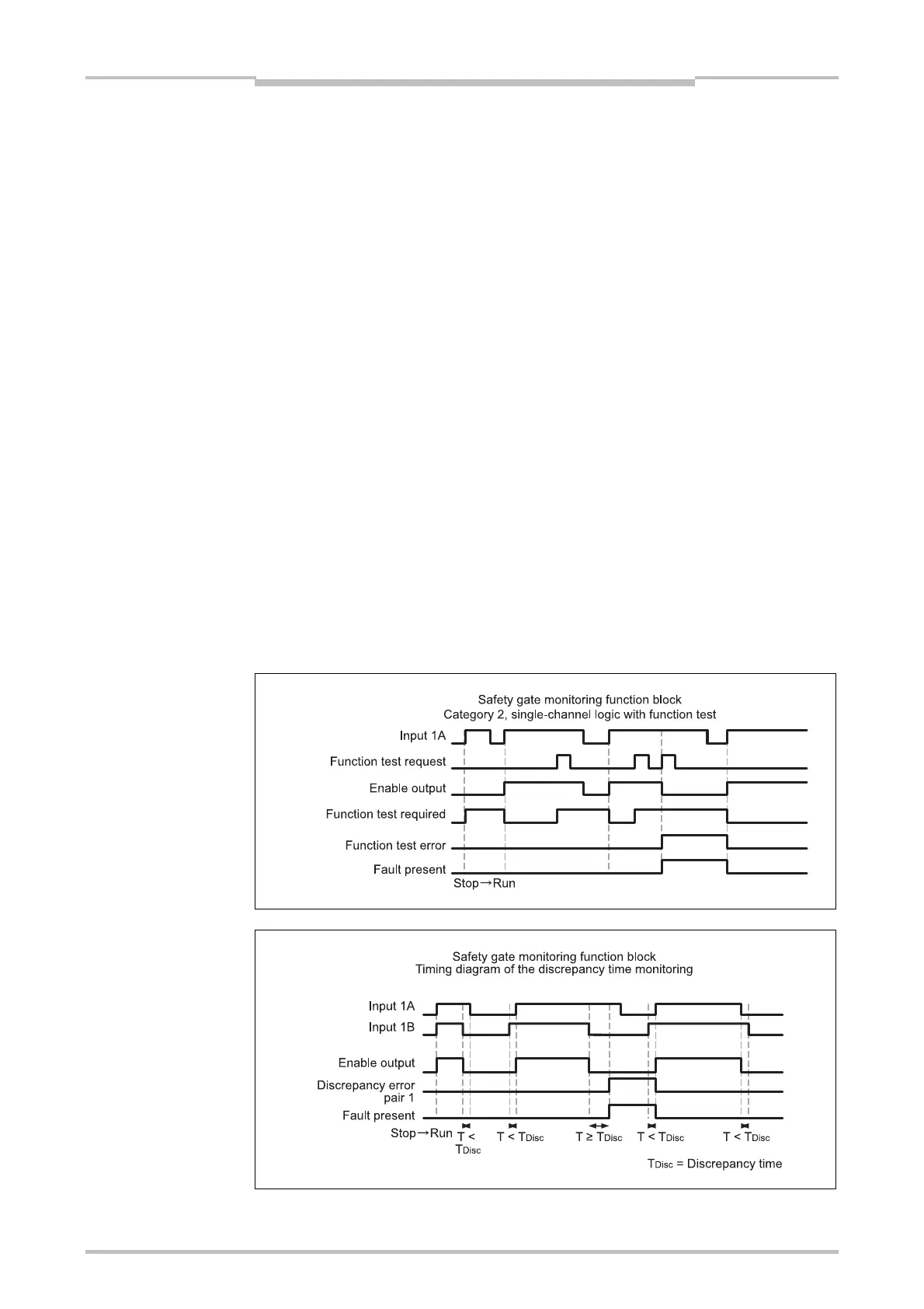
Sequence/timing diagrams
Figure 183:
Sequence/timing diagram
for the Safety gate
monitoring function block,
Category 2, single-channel
with function test
Figure 184:
Sequence/timing diagram
for the Safety gate
monitoring function block,
Category 4, dual-channel
equivalent (1 pair) without
function test

 Loading...


