Chapter 9
235
Logic programming – Function blocks
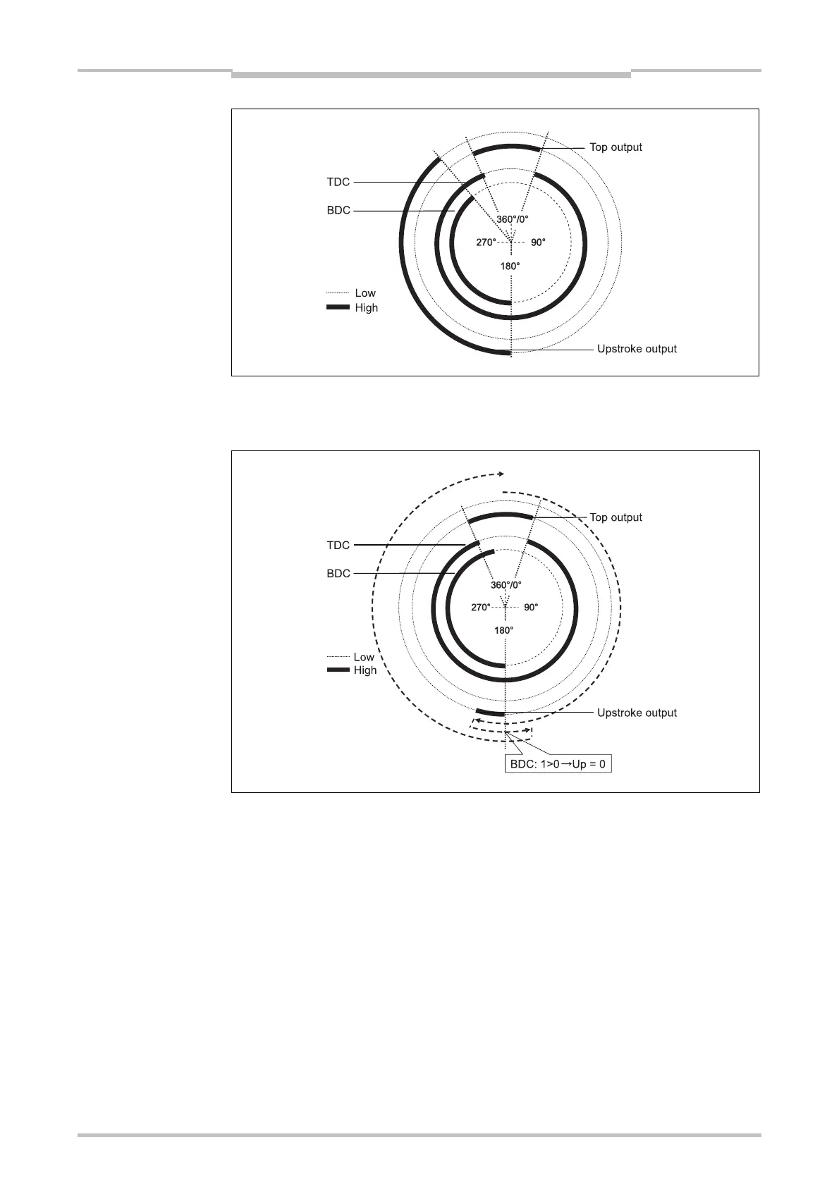
A second rising edge of the BDC input does not restart the upstroke phase. This is the
case if Number of BDC signals per cycle is 0-2 (e.g. hydraulic press), and the press
moves back and forth in the bottom section.
If in this setting no BDC pulse at all occurs during the cycle, the Upstroke output will
remain Low for the complete cycle.
If the BDC input is already High when the monitoring of the contact inputs begins (e.g.
in the first logic cycle, after resetting an error or after enabling monitoring with Disable
monitoring input), the Upstroke output will remain Low during the first cycle. The
next BDC transition from Low to High is only accepted after a transition from High to
Low has occurred at the Top output.
Figure 219:
Press cycle for the Universal
press contact function block
with falling edge of BDC
before TDC
Figure 220:
Press cycle for the Universal
press contact function block
with 2 BDC transitions
Note

 Loading...


