4G9 ENGINE (E-W)
-
Crankshaft, Cylinder Block, Flywheel and Drive Plate
11A-12-3
PWEE9502-A
E
Nov. 1995Mitsubishi Motors Corporation Revised
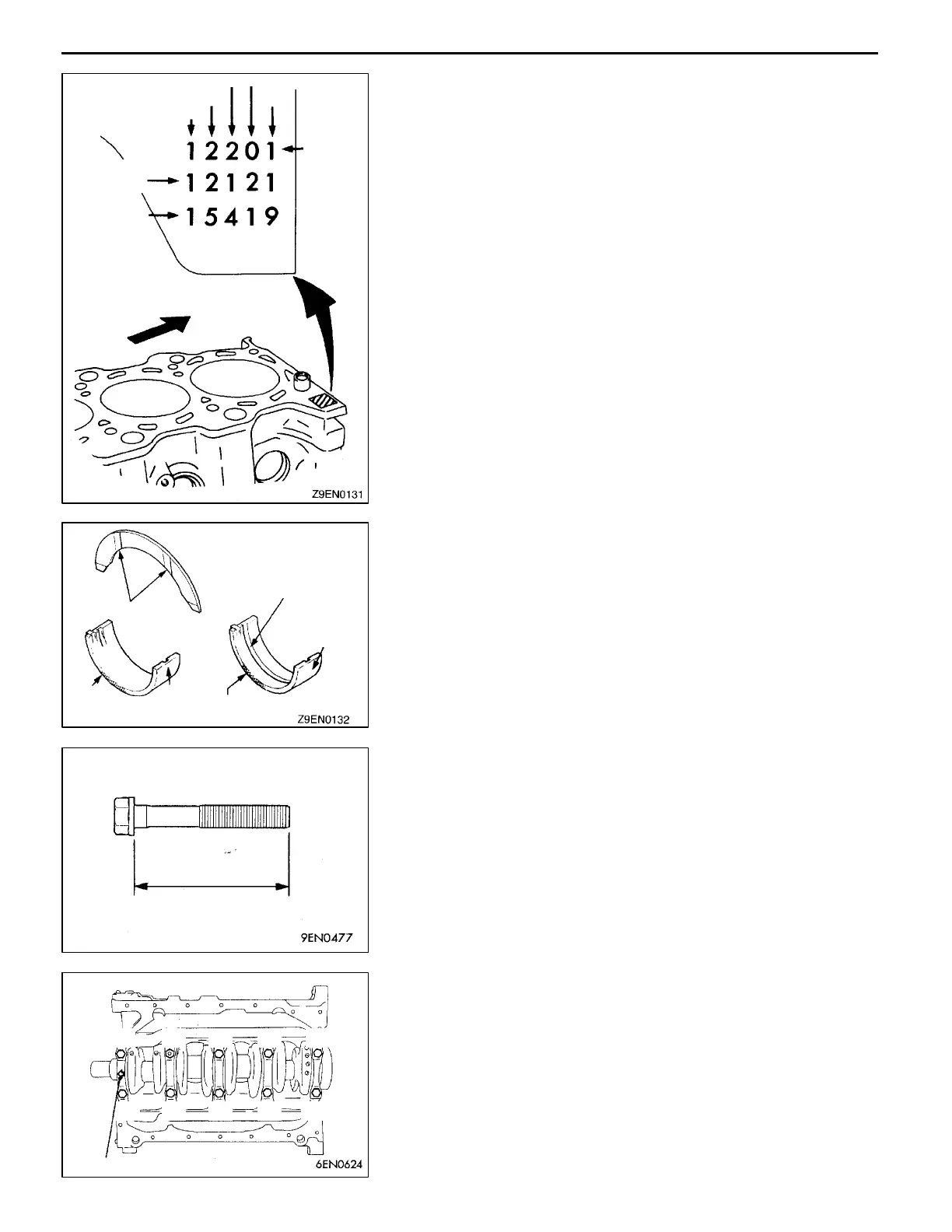
(2) Install the bearings having an oil groove to the cylinder
block.
(3) Install the bearings having no oil groove on the bearing
caps.
(4) Install the thrust bearings at the No. 3 upper bearing
with the grooved side towards the crank web.
"
C
A
BEARING CAP/BEARING CAP BOLT INSTALLATION
(1) Install the bearing caps so that their arrows are positioned
on the time belt side.
(2) When installing the bearing cap bolts, check that the
shank length of each bolt meets the limit. If the limit is
exceeded, replace the bolt.
Limit: max. 71.1 mm
(3) Apply engine oil to the threaded portion and bearing
surface of the bolt.
(4) Tighten the bearing cap bolts to 25 Nm torque in the
tightening sequence.
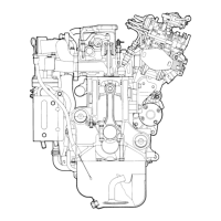
Cylinder I.D.
identification
mark
Serial No.
Front
No. 1
No. 2
No. 3
No. 4
No. 5
Identifica-
tion mark
for cylin-
der block
bearing
support
section
I.D.
Grooves
Identification
colour
Identifica-
tion colour
Oil groove
Identification
colour
Identification
mark
Length of shank
Arrow
(8) (4) (1) (5) (9)
(7) (3) (2) (6) (10)
 Loading...