4G9 ENGINE (E-W) -
Injector and Fuel Pump Assembly (GDI)
11A-6c-1
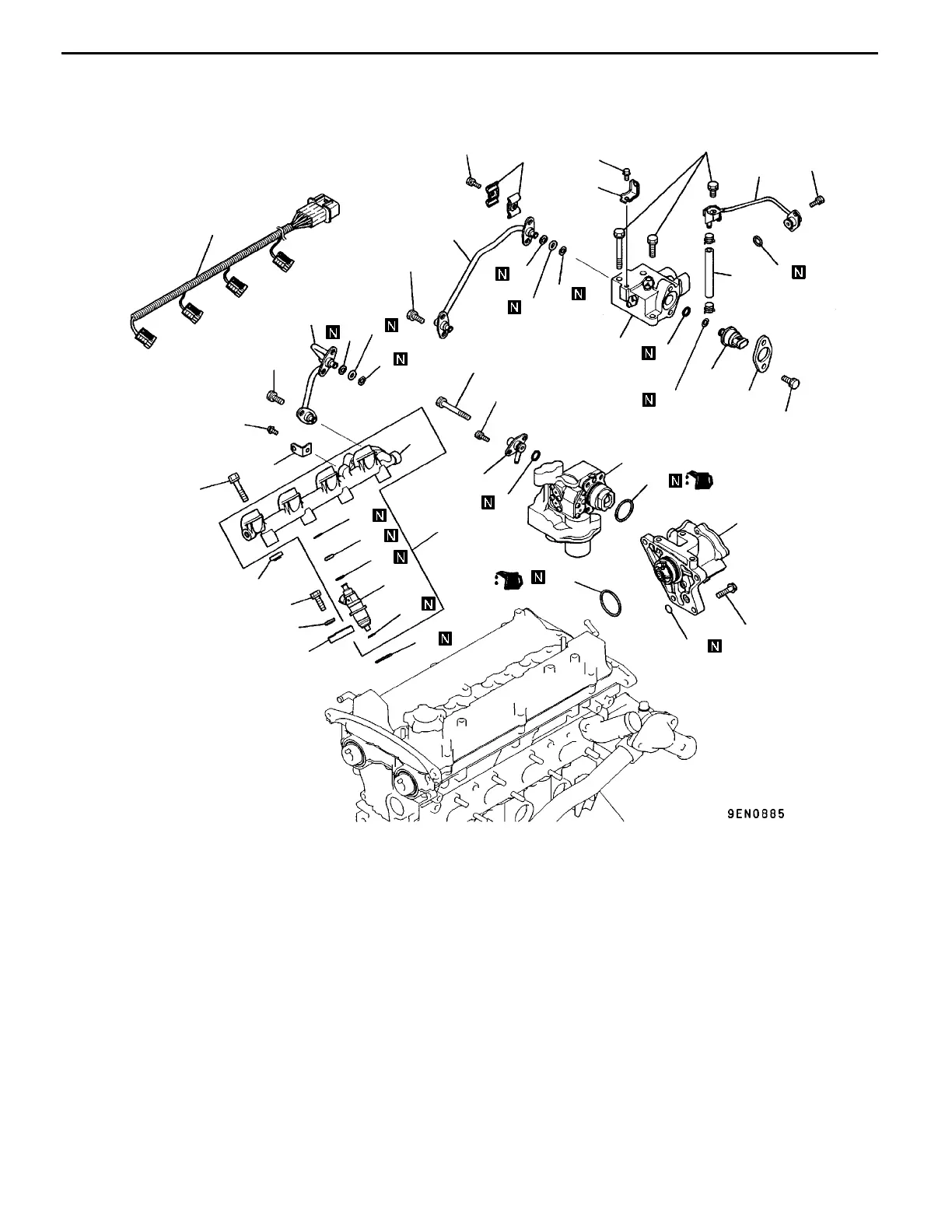
6c. INJECTOR AND FUEL PUMP ASSEMBLY (GDI)
REMOVAL AND INSTALLATION <For CARISMA>
18 Nm
17
±
2Nm
9Nm
14
13
8
11
10
12
1
9
5
6
7
3
2
15
4
16
17
18
19
20
28
30
21
29
25
26
27
23
22
24
38
31
35
36
37
33
32
34
11 Nm
23 Nm
22 Nm
9Nm
9Nm
11 Nm
11 Nm
11 Nm
11 Nm
23 Nm
Removal steps
1. Fuel hose
2. Fuel low pressure pipe
3. O-ring
4. Fuel nipple
5. O-ring
6. Clamp
"
F
A 7. Fuel feed pipe
8. Backup ring
9. O-ring
10. Backup ring
"
F
A 11. Fuel pump
12. O-ring
13. Harness bracket
14. Fuel return pipe
15. Backup ring
16. O-ring
17. Backup ring
"
E
A 18. Fuel high pressure regulator
19. Flange
"
D
A 20. Fuel pressure sensor
21. O-ring
22. Backup ring
"
C
A 23. Pump camshaft case
24. O-ring
25. O-ring
26. Harness bracket
27. Injector harness
28. Washer
29. Injector holder
"
B
A 30. Delivery pipe and injector
31. Insulator
32. Injector gasket
33. Injector
"
A
A 34. Corrugated washer
"
A
A 35. Backup ring
"
A
A 36. O-ring
"
A
A 37. Backup ring
38. Delivery pipe
PWEE9502-E
E
Dec. 1998Mitsubishi Motors Corporation Revised
 Loading...