Pipe connections are made at the location as illustrated.
It is necessary to connect hot water tank or buffer vessel even if hot water supply is not necessary.
HT30MT500
Connection of external heat source (Page 9 in installation manual)
MT500
Connect an external heat source such as gas or oil boiler to (XL8)(in) and (XL9)(out) on tank
unit(dimension G1 internal).
Remove the insulation lid which covers the port XL8 and XL9, and attach Cover on the edge of insulation
for better appearance.
Refer to the dimension drawing for connecting part XL8 and XL9 in this sheet.
For external heat source controlled by the indoor unit, disconnect the sensor on BT19, connect the
attached sensor as supplied parts on the same terminal instead and put it on BT24. It is recommended to
apply thermal silicone paste on the sensor element for better measurement.
For external heat source controlled independently, put the temperature sensor of it on BT24 to control it
appropriately.
XL4
(To hot domestic water)
XL24
(From XL21)
XL3
(From cold
domestic water)
XL23
(To XL22)
Electrical components (Tank) (Page 13 in installation manual)
HT30MT500
Connection between indoor unit and tank (Page 14 in installation manual)
HT30
Connect the terminal as shown in the following figure.
It is not necessary to connect any wiring on the terminal No13 and No14 on AA22-X4.
Explanation
Symbol Contents
Scale length of
conductor (mm)
X100 Terminal block, incoming supply to tank 13
X101 Terminal block, sensor from indoor unit 9
BT30 Thermostat, standby mode
FD1 Temperature limiter
X100 X101
BT19
BT24
XL8
XL9
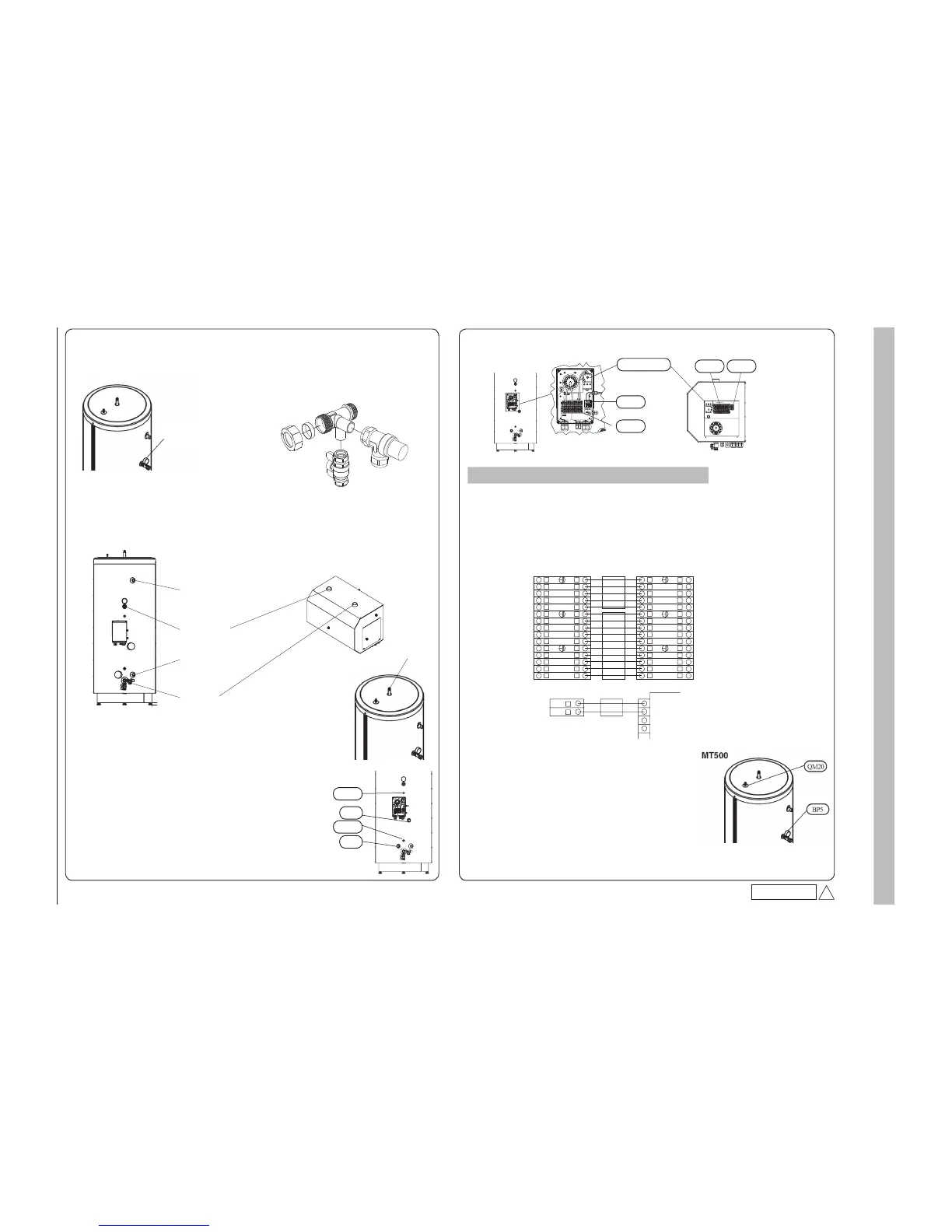
Connecting hot water heater / buffer vessel (Page 8 in installation manual)
For MT500,install joints and relevant components as illustrated before connecting pipes.
<T connection with Mamometer>
Fasten it on XL24 so that the Mamometer comes on top.
For MT500,remove handing rod on top after installation and plug the hole with Isolation plug attached.
Hanging rod
Venting the climate system (Page 19 in installation manual)
1. Vent tank unit through the air vent valve (QM20) and the rest of the heating system
through the relevant venting valves.
2. Open the valve to expansion vessel when air vent is completed.
3. After opening the valve, vent indoor unit through venting valve on indoor unit to
bleed rest of air completely.
Keep topping up and venting until all air has been removed and the correct pressure
has been obtained.
PSB012D983
A
<X connection>
1) Fasten it on XL23 so that the pipe for Ball valve is downwards.
2) Fasten Ball valve on the bottom pipe.
3) Fasten Safety valve on the side pipe so that drain outlet is downwards.
Commissioning (Page 19 in installation manual)
HT30
Indoor unit
7. Select "Service" in menu 8.1.1.
Set operating mode to "No HW" in menu 9.3.14.
X101
X100
FD1-BT30
 Loading...

