Emptying the vessel (Page 6 in installation manual)
The vessel in indoor unit is emptied by opening the valve (QM1) and safety valve (FL2) on the tank.
HT30MT500
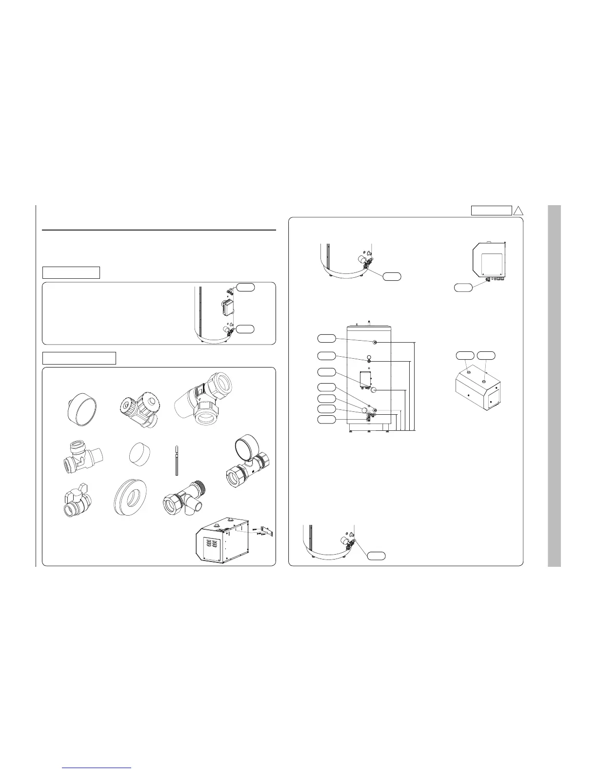
Dimensions and pipe connections (Page 7 in installation manual)
<Tank unit>
MT500
XL3 Cold water (G1 external)
XL4 Hot water (G1 external)
XL8 External heat source in (G1 internal)
XL9 External heat source out (G1 internal)
XL23 Circulation supply (outlet) (28mm)
XL24 Circulation return (inlet) (28mm)
QM1 Valve
HT30
XL23 Circulation supply (outlet) (G1 external)
XL24 Circulation return (inlet) (G1 external)
QM1 Valve
XL4
XL24
XL8
XL3
XL9
XL23
QM1
QM1
XL24 XL23
QM1
Installation and instruction sheet for MT500 and HT30
Note
This installation and instruction sheet is a supplement sheet for installation manual and user's manual for HMS140V attached in the outdoor unit.
Refer to the installation manual and instruction manual attached in outdoor unit for details.
User's manual
The climate system’s safety valve (Page 13 in user's manual)
MT500
This unit has been equipped with a safety valve for the water heater as illustrated.
Check must be carried out regularly with the way which is shown in user's manual.
HT30
A safety valve is supplied with tank unit and the safety valve is installed to water pipe
by installer.
Check must be carried out regularly with the way which is shown in user's manual.
Installation manual
Supplied components (Page 5 in installation manual)
Following parts are supplied with tank unit. Install below parts according to installation manual.
HT30
BP5
FL2
MT500 HT30
Connecting the climate system (Page 8 in installation manual)
The location of the safety valve (FL2)
MT500
The safety valve (FL2) must be installed on tank unit as illustrated.
HT30
The safety valve is supplied with tank unit.
Install the supplied safety valve to water pipe returning to indoor unit.
FL2
Safety valve
Drainage valveManometer
PSB012D983
Hanging indoor unit on a wall (Page 5 in installation manual)
HT30
Fix the bracket on the wall and hang the HT30 as same way as indoor unit.
A
MT500
Safety valve
Isolation plug
Temp sensor
BT24
T connection
with Manometer
Ball valve Cover X connection
 Loading...

