-
70
-
Installation
'10 • HM-T-149
Miniature circuit-breaker (FA1, FA2, FA3)
Theautomaticheatingcontrolsystem,circulationpumpsand
theirwiringinindoorunit,areinternallyfuseprotectedwitha
miniature circuit breaker (FA1).
Outdoor unit and equipment are internally fuse protected in
indoorunit,withaminiaturecircuitbreaker(FA2).
Tank unit and equipment are internally fuse protected in indoor
unit with a miniature circuit breaker (FA3).
Temperature limiter (FD1)
The temperature limiter (FD1) cuts the current supply to the
electrical heater if the temperature rises up between 90 and
100°C and can be manually reset.
Resetting
The temperature limiter (FD1) is accessible behind the front
cover.Thetemperaturelimiterisresetbyrmlypressinginits
button.
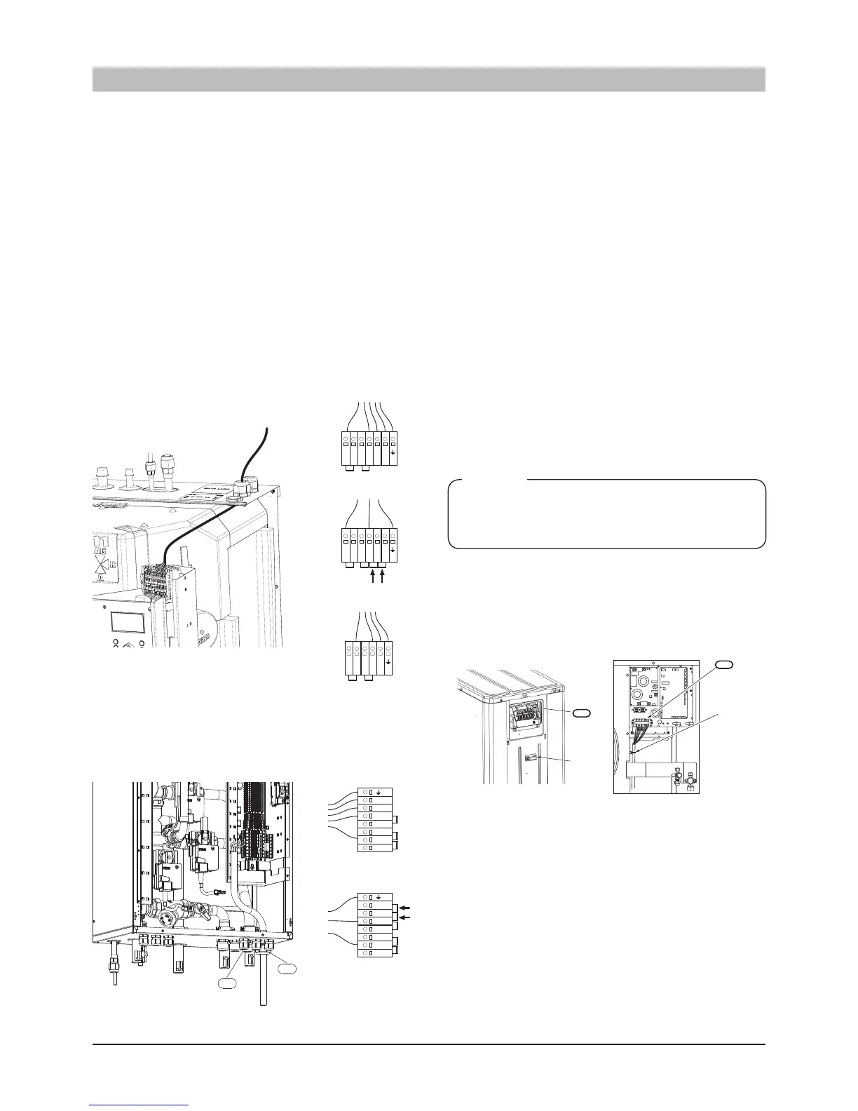
Connection between indoor unit and outdoor unit
The cable between the units must be connected between
terminal block for incoming supply (TB) in outdoor unit and
terminal block (X2) in indoor unit via cable gland (UB2).
FDCW71 FDCW100, 140VNX
Note!
■ Outdoorunitmustbeearthedbeforethewiringbetweenthe
units is connected.
■ Thewiring mustbeattachedsothat theterminalblockis
not put under stress.
■ Scalelengthofconductoris8mm.
Connectphase(brown),neutral(blue),communication(black
and grey) as well as earth (yellow/green) as illustrated:
Iutdoor unit installation
Connecting the supply
Incoming supply is connected on terminal block (X1) via cable
gland (UB1). The cable must be dimensioned according to the
applicable norms.
HM270V can be connected with either 400 V 3NAC or 230 V
1AC.
400 V 3NAC/230V 3AC
: Connect incoming supply according
to the markings on terminal (X1).
230 V 1AC
: Install the supplied straps between terminals L1
and L2 as well as between L2 and L3 on incoming terminal
block (X1). Connect incoming supply according to the terminal
markings.
<HMA100V, HMA100VM>
<HMS140V>
 Loading...

