moog
MSD Servo Drive DC-AC Operation Manual
[]
Electrical
installation
29
Id.-No.: CA97554-001 Date: 06/2012
to glossaryto table of contents
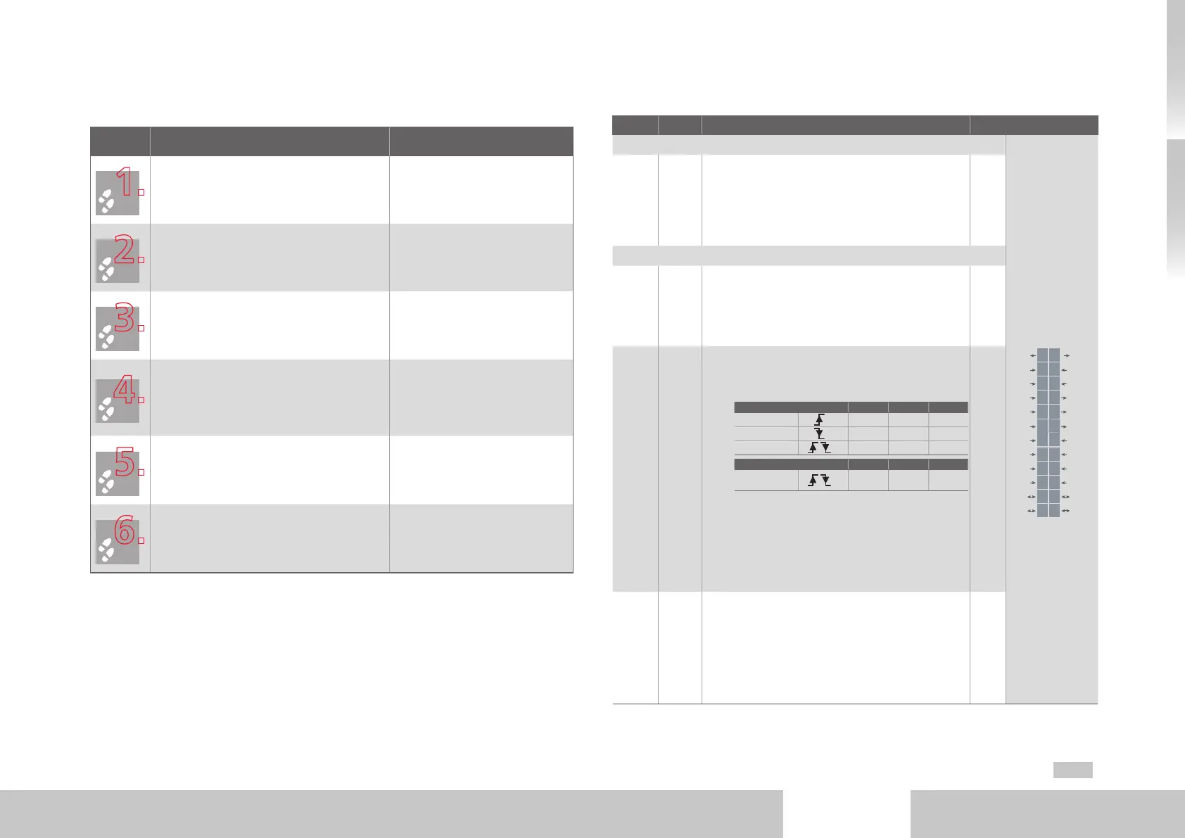
3.7 Control connections
Step Action Comment
Check whether a complete device setup is
already available, i.e. whether the drive has
already been configured.
If this is the case, a special control terminal
assignment applies.
Please contact your project engineer to ob-
tain the terminal assignment!
Choose a connection assignment.
Wire the control terminals with shielded
cables.
The following is strictly required: STO request
X4/22, ENPO X4/10 and a start signal (with
control via terminal).
Ground the cable shields over a
wide area on both sides.
Cable corss-sections: 0.2 to
1.5mm²,with ferrules with plastic
sheath max.0.75mm²
Keep all contacts open (inputs inactive).
Check all connections again!
3.7.1 Specification of control connections
Des. Term. Specification Isolation
Analog inputs
REL
REL
ISDSH
ISD06
ISD05
ISD04
ISD03
ISD02
ISD01
ISD00
+24V
DGND
RSH
RSH
ENPO
OSD02
OSD01
OSD00
ISA1-
ISA1+
ISA0-
ISA0+
+24V
DGND
24
23
22
21
20
19
18
17
16
15
14
13
12
11
10
9
8
7
6
5
4
3
2
1
ISA0+
ISA0-
ISA1+
ISA1-
X4/3
X4/4
X4/5
X4/6
• U
IN
=±10VDC
• Resolution 12Bit; R
IN
approx.101kΩ
• Terminal scan cycle "IP mode" 125µs, otherwise
1ms
• Tolerance: U±1% of the measuring range end
value.
no
Digital inputs
ISD00
ISD01
ISD02
ISD03
ISD04
X4/15
X4/16
X4/17
X4/18
X4/19
Default input
• Frequency range <500Hz
• Scan cycle: 1ms
• Switching level Low/High: ≤4.8V/≥18V
• I
MAX
at+24V = 3mA typ.
yes
ISD05
ISD06
X4/20
X4/21
Touchprobe or default input
• Input Touchprobe for fast storage of process data
(e.g. actual position)
− Internal signal delay
Hardware-Version 0..1 Min. Max. Typ.
ISD05
3µs 16µs 8µs
ISD05
4µs 27µs 15µs
ISD06
2µs
from Hardware-Version 2 Min. Max. Typ.
ISD05 +
ISD06
2µs
− Activation via ISD05/ISD06 = 15(PROBE)
• Default input
− Frequency range ≤500Hz
− Scan cycle: 1ms
• U
IN max
= +24VDC +20%
• I
IN max
at+24VDC =10mA, R
IN
=ca. 3kΩ
• Switching level Low/High: ≤4.8V/≥18V
yes
ENPO X4/10
• Disable restart inhibit (STO) and enable power-
stage = High-level
• OSSD-capable (from hardware version 2)
• Reaction time approx. 10ms
• Switching level Low/High: ≤4.8V / ≥18V
• U
IN max
= +24VDC +20%
• I
IN
at +24VDC = typ. 3mA
yes
Table 3.4 Specification of control connections X4

 Loading...


