moog
MSD Servo Drive DC-AC Operation Manual
12
Id.-No.: CA97554-001 Date: 06/2012
to glossaryto table of contents
2.2 DC-AC servo drive installation
Air-cooled housing
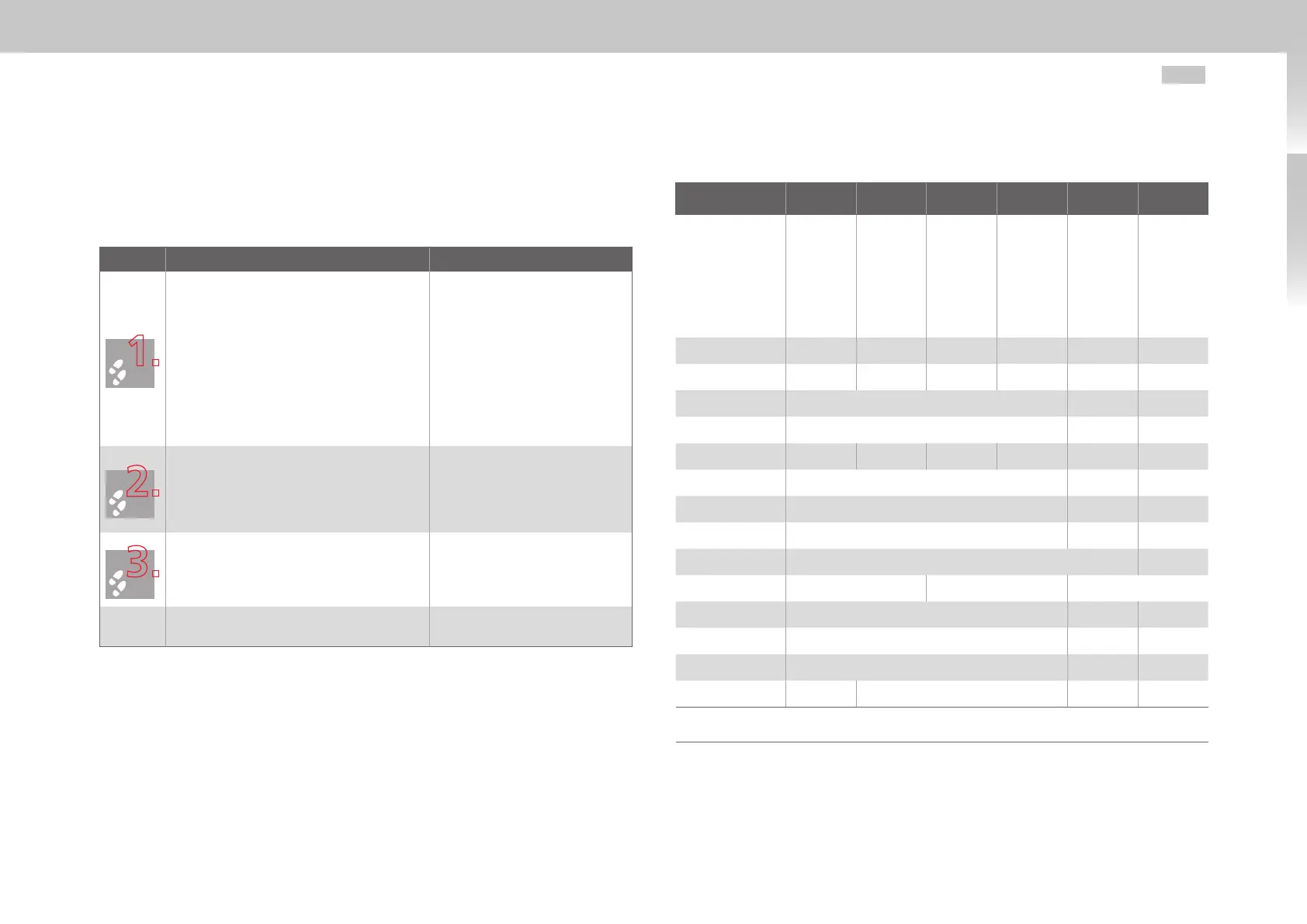
Step Action Comment
Arrange the devices starting from the power
supply unit to the right and/or left sorted in
descending order of power output, in order to
minimize thermal influences.
In the case of the power supply unit Size 5,
align all MSD Servo Drive DC-AC devices in a
line along the top edge of the unit
(see Fig. 2.5).
In the case of the power supply unit Size 6A,
align all MSD Servo Drive DC-AC devices
18.5 mm lower (see Fig. 2.6).
This is necessary in order to ex-
ecute the DC link using the ready
made-up cables.
For specified mounting clearances-
see Table 2.1.
Mark out the position of the tapped holes on
the backing plate.
Drill holes in the backing plate and cut a
thread for each fixing screw.
Take account of the bend radius of
the connecting cables!
For hole pitch and dimensional
drawings see Table 2.1, Fig. 2.1 and
Fig. 2.2.
Mount the DC-AC servo drives vertically in a
row on the back plane.
The contact area must be metal-
lically bright. For the DC power
supply use the supplied ready
made-up DC link cables.
Continue with the electrical installation in
section3.
Dimensions and mounting distances for air-cooled housing
MSD Servo Drive Size 1 Size 2 Size 3 Size 4 Size 5 Size 6A
G393-004
G393-006
G393-008
G393-012
G393-016
G393-020
G393-024
G393-032
G393-045
G393-060
G393-072
G393-090
G393-110
G393-143
G393-170
Weight [kg] 3.4 4.9 6.5 7.5 13 32
B (width) 58.5 90 130 171 190 280
H (height)
1)
295 345 540
T (depth)
1)
224 240 322
A 29.25 50 80 120 150 200
C 382 406.5 581
C1 5 6 10
D 4.8 5.6 9.5
E Direct side by side mounting, maximum 2 40
2)
F
3)
≥100 ≥150 ≥18 0
G
3)
≥270 ≥300 ≥500
H1 392 418.5 600
H2 38.5 15 20
Screws 2 x M4 4 x M4 4 x M5 4 x M8
1) without terminals/connectors 3) The bend radius of the connecting cables must be taken into account
2) Mounting clearance of Size 6A to other Size 6A units All dimensions in mm
Table 2.1 Dimensions and mounting distances for air-cooled housing

 Loading...


