moog
MSD Servo Drive DC-AC Operation Manual
30
Id.-No.: CA97554-001 Date: 06/2012
to glossaryto table of contents
Des. Term. Specification Isolation
Digital outputs
REL
REL
ISDSH
ISD06
ISD05
ISD04
ISD03
ISD02
ISD01
ISD00
+24V
DGND
RSH
RSH
ENPO
OSD02
OSD01
OSD00
ISA1-
ISA1+
ISA0-
ISA0+
+24V
DGND
24
23
22
21
20
19
18
17
16
15
14
13
12
11
10
9
8
7
6
5
4
3
2
1
OSD00
OSD01
OSD02
X4/7
X4/8
X4/9
• No destruction in case of short-circuit (+24V ->
GND), but device may briefly shut down
• I
MAX
=50mA, PLC-compatible
• Terminal scan cycle =1ms
• High-side driver
yes
STO (Safe Torque Off)
ISDSH
(STO)
X4/22
• "Request input" = Low-level
• OSSD-capable (from hardware version 2)
• Switching level Low/High: ≤4.8V / ≥18V
• U
IN max
= +24VDC +20%
• I
IN
at +24VDC = typ. 3mA
yes
RSH
RSH
X4 /11
X4/12
Diagnosis STO, both tripping chan-
nels active, one NO contact with au-
tomatically resetting circuit-breaker
(polyswitch)
• 25V/200mAAC, cosϕ=1
• 30V/200mADC, cosϕ=1
X4/12
X4/11
yes
Relay outputs
REL
X4/23
X4/24
Relay, 1 NO contact
• 25V/1.0AAC, cosϕ=1
• 30V/1.0ADC, cosϕ=1
• Switching delay approx.10ms
• Cycle time1ms
X4/23
X4/24
Auxiliary voltage
+24V
X4/2
X4/14
• Auxiliary voltage to feed the digital control inputs
• U
H
= U
V
-∆U (∆U typically approx.1.2V), no de-
struction in case of shot-circuit (+24V -> GND),
but device may briefly shut down.
• I
MAX
=80mA (per pin) with self-resetting circuit-
breaker (polyswitch)
yes
Digital ground
DGND
X4/1
X4/13
Reference ground for +24V, I
MAX
=80mA (per pin),
Hardware versions 0..1 with self-resetting circuit-
breaker (polyswitch)
yes
Table 3.4 Specification of control connections X4
ATTENTION! With high currents flowing through the ground terminals a high
resistance isolation from the device ground is required. This may cause incor-
rect response of the drive (avoid ring currents in the wiring).
NOTE: Note that in the event of a fault the supply unit may no longer be able
to feed regenerative power from the DC-AC servo drives back into the grid.
In order to prevent destruction of the supply unit braking resistor in sustained
regenerative mode, the DC-AC servo drives and power supply unit can be
mutually locked via X4. For more information and an example of circuit con-
figuration refer to appendix on page 83.
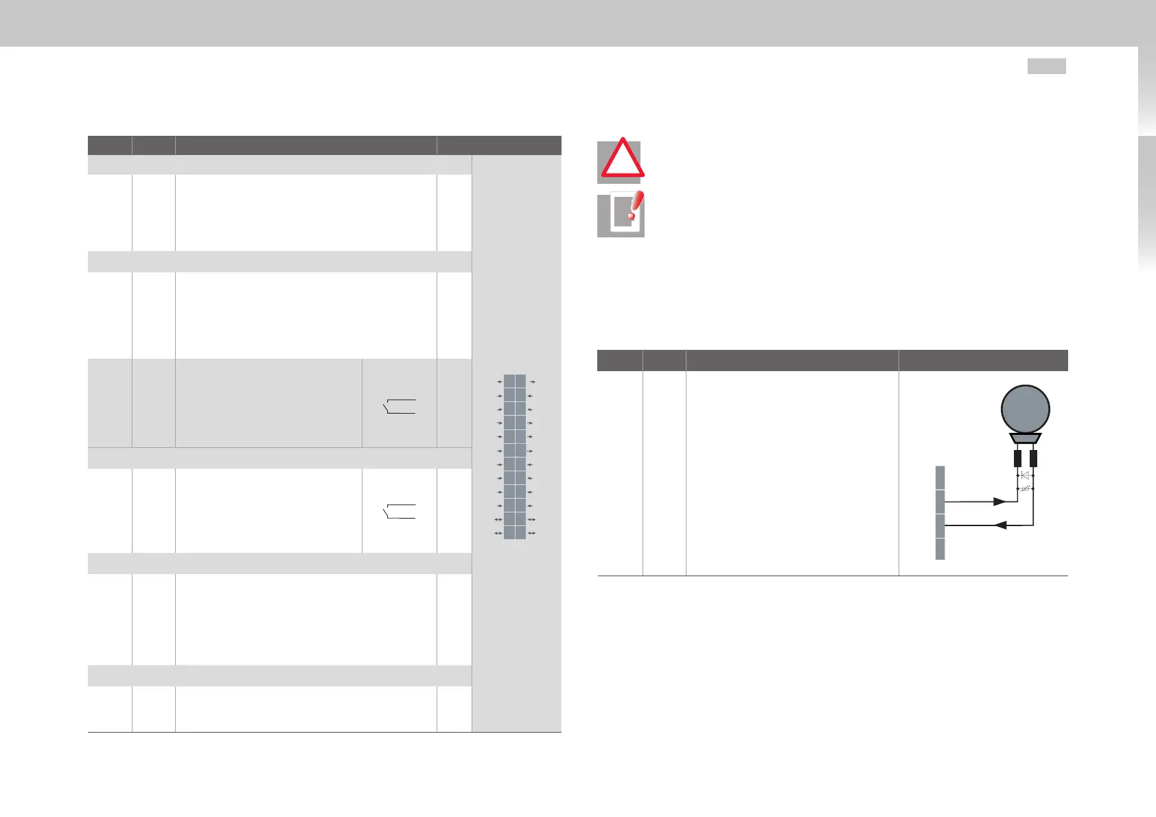
3.7.2 Brake driver
Connector X13 (Size 1 to Size 4) is intended for connection of a motor brake.
Des. Term. Specification Connection
+24V
BR+
BR-
GND
X13/1
X13/2
X13/3
X13/4
• Short-circuit-proof
• Voltage supply is via the control supply
U
V
on X9 or X10
• U
BR
=U
V
-∆U`(∆U`typically ap-
prox.1.4V)
• To actuate a motor holding brake up
to I
BR
=2.0Amax., for brakes with
higher current requirements a relay
must be interposed.
• Overcurrent causes shutdown
• Also usable as configurable digital
output.
• Interruptible cable break monitoring
<500mA in condition "1" (up to relay)
M
Brake (+)
Brake (-)
X13
1
BR+ 2
BR- 3
4
Table 3.5 Specification of terminal connections X13
!

 Loading...


