moog
MSD Servo Drive DC-AC Operation Manual
36
Id.-No.: CA97554-001 Date: 06/2012
to glossaryto table of contents
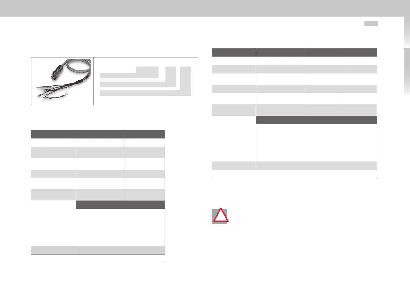
3.13.2 Ready made-up motor cable
CO8336 - xxx yyy
1)
Ready made-up motor cable
Configuration option
Cable length (m)
1) yyy stands for length in meters; standard length: 1 m, 5 m, 10 m, 15 m, 20 m, 50 m. Further length on request
Motor cable CO8336-xxx-yyy Order code
Technical data motor cable
Technical data C08336-xxx-yyy
1),2)
CB05708-xxx-yyy
1),2)
Continous rated current 10A TBD
Surge current
30A (90s at +72.7°C)
(+162.9°F)
TBD
Minimum bend radius
In fixed installation: 60mm
In flexible use: 120mm
TBD
Cable diameter range 9 to 14.4mm TBD
Cable cross-section
4 x 1.5mm² +
2 x 1mm²
4 x 4mm² +
2 x 1.5mm²
Temperature range
-50°C to +90°C
(-58°F to +194°F)
TBD
Wiring
Connector pin / Wiring
2 / U
4 / VV
1 / WWW
PE / yellow; green
5 / Brake +; white
6 / Brake -; black
Connector housing / Screen
Connector type Size 1
2)
xxx-001 for standard configuration option, others on request
Table 3.12 Technical data motor cable (Connector type Size1)
Technical data C08733-xxx-yyy
1),2)
B47916-xxx-yyy
1),2)
CA98676-yyy
1),2)
Continous rated current 44A 61A 82A
Surge current TBD
Minimum bend radius
In fixed installation: 60mm
In flexible use: 120mm
TBD
Cable diameter range 16.2 ±3mm TBD
Cable cross-section
4 x 6mm² +
2 x 1mm²
4 x 10mm² +
2 x 1.5mm²
4 x 16mm² +
2 x 1.5mm²
Temperature range
-50°C to +90°C
(-58°F to +194°F)
TBD
Wiring
Connector pin / Wiring
U / U
V / VV
W / WWW
PE / yellow; green
+ / Brake +; white
- / Brake -; black
Connector housing / Screen
Connector type Size 1.5
2)
xxx-001 for standard configuration option, others on request
Table 3.13 Technical data motor cable (Connector type Size1.5)
3.13.3 Switching in the motor cable
ATTENTION! Switching in the motor cable must take place with the power
cut and the power stage disabled, as otherwise problems such as burned-
off contactor contacts may occur. In order to ensure unpowered switch-on,
you must make sure that the contacts of the motor contactor are closed
before the servo drive power stage is enabled. At the moment the contactor
is switched off it is necessary for the contact to remain closed until the servo
drive power stage is shut down and the motor current is 0. This is done by
inserting appropriate safety times for switching of the motor contactor in the
control sequence of your machine.
Despite these measures, the possibility cannot be ruled out that the servo drive may
malfunction during switching in the motor cable.
!

 Loading...


