moog
MSD Servo Drive DC-AC Operation Manual
22
Id.-No.: CA97554-001 Date: 06/2012
to glossaryto table of contents
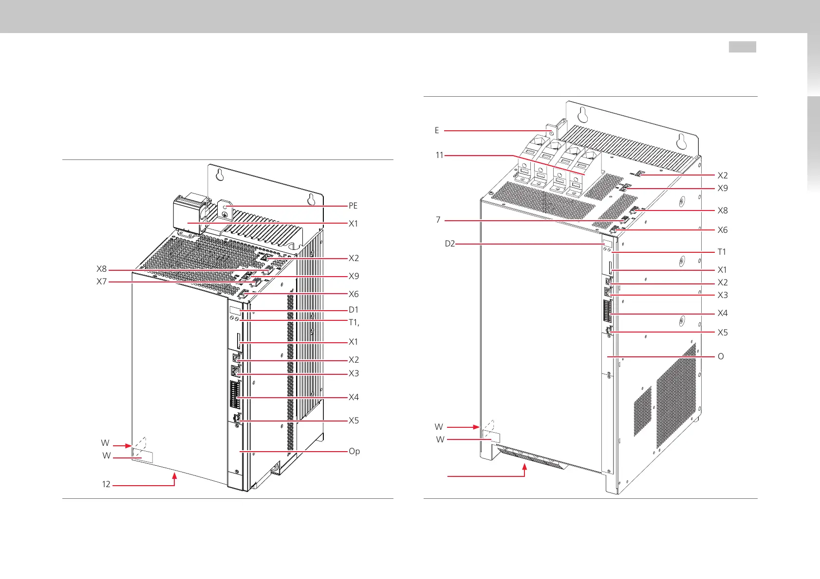
3.3 Overview of connections Size 5 and Size 6A
The following shows the layout, with the corresponding positions of plugs and terminals.
To aid orientation, the connectors and terminals are labelled by abbreviations.
Fig. 3.3 Layout Size 5 (without shields)
Fig. 3.4 Layout Size 6A (without shield)
PE
X11
X20
X9, X10
X6
D1, D2
T1, T2
X1
X2
X3
X4
X5
Option1
X8
X7
SW
HW
X12
X20
X9, X10
X8
X6
T1/T2
X1
X2
X3
X4
X5
Option1
PE
X11
X7
D1, D2
SW
HW
X12

 Loading...


