moog
MSD Servo Drive DC-AC Operation Manual
[]
Electrical
installation
21
Id.-No.: CA97554-001 Date: 06/2012
to glossaryto table of contents
USB 1.1
MMC slot
ISD00
ISD01
ISD02
OSD02
Relay
ENPO (STO)
Motor
3
Option 2
Control
Service
interface
ISDSH (STO)
ISA00+
ISA00-
ISA01+
ISA01-
Analog set point 1
+24 V DC against
I/O-GND
+24 V (U
H
)
3
4
5
6
10
15
16
17
9
23
24
22
RSH
Diagnostic
STO
12
11
1
2,14
13
I/O-GND
Relay
Digital2
L+
L-
U
V
W
6
8
ISD03
ISD04
ISD05
18
19
20
ISD0621
OSD01
8
Digital1
OSD00
7
Digital0
+
-
DC link
(Do not connect anything!)
OSD04
54321
10 9876
15 14 13 12 11
DGND
DGND
43 21
9876
~
D1, D2
T1, T2
Ethernet
DC -
DC +
PE
DC -
DC +
X11
X10
X9
X1
X2
X3
X4
X8
X7
X6
X5
X13
X12
Front
Option 1
V
)
MMC
MultiMediaCard
INSERT
Communication
Fieldbusses
Resolver
-
+
-
+
Encoder
Technology
1
2
1
2
Top side
Bottom
DC-L
Motor brake actuation
GND
1
2
3
4
Do not connect X13/1!
Do not connect X13/4!
24 V DC
Supply for
control electronics (U
Service
interface
Analog set point 2
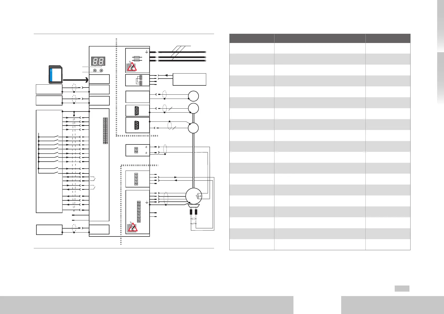
Fig. 3.2 Connection diagram Size 1 to Size 4
Abbr. Designation Details
D1, D2 7-segment display page42
T1, T2 Pushbuttons page42
X1 Slot for MMC card page41
X2 USB 1.1 interface page31
X3 Ethernet interface page31
X4 Terminals page29
Option1 Communication page31
X11 Connection DC supply page27
DC- L DC link cables page79
PE Connection protective conductor page24
X9, X10 Connection control supply page26
X8 (Option2) Technology page31
X7 Connection high-resolution encoder page34
X6 Connection resolver page33
X5 Connection motor temperature sensor page 35
X13 Connection motor brake page30
X12 Connection motor page35
HW Hardware name plate page5
SW Software name plate -
Table 3.1 Key to connection diagram Size 1 to Size 4

 Loading...


