moog
MSD Servo Drive DC-AC Operation Manual
38
Id.-No.: CA97554-001 Date: 06/2012
to glossaryto table of contents
4.2.1 Switching on control voltage
For initialization and parameter setting, first switch on only the 24 V con-
trol voltage. Do not yet switch on the power supply.
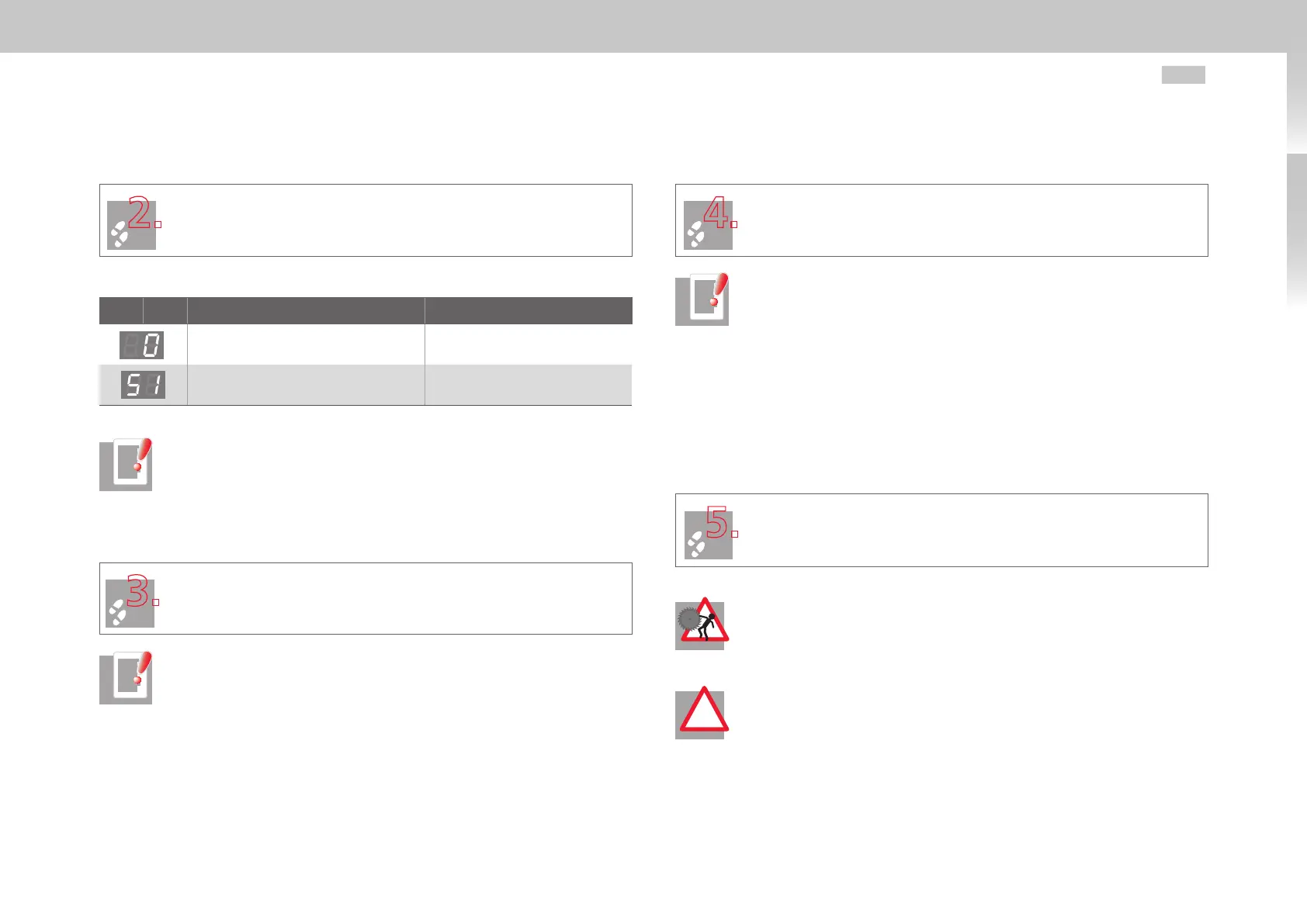
Display readout after switching on the control supply
D1 D2 Action Explanation
Switch-on of ext. 24 V control voltage Initialization in progress
Initialization complete Not ready for start
Table 4.1 Switch-on status of MSD Servo Drive (after connection of the 24 V DC control voltage)
NOTE: For details on the control supply refer to section3.6 “Connection of
supply voltage” starting on page26.
4.2.2 Connecting the PC and servo drive
The PC can be connected to the servo drive via USB or Ethernet
(TCP/ IP). Connect the PC and servo drive to the corresponding cables.
NOTES:
• Initialization
Communication between the PC and the servo drive can only be stab-
lished once the servo drive has completed its initialization.
• USB driver and TCP/IP configuration
If the PC does not detect the connected servo drive, check the driver and
the settings of the relevant interface (see Moog
DriveADministr Ator5 Instal-
lation Manual).
4.2.3 Parameter setting
For drive system setup Moog DriveADministrAtor5 includes a Commission-
ing Wizard.Start the Wizard.
NOTES:
• Online help
For a detailed description of Moog DriveADminist rAtor5 and of the Com-
missioning Wizard, refer to the Moog
DriveADministr Ator5 Online Help.
• Motordata set
When using Moog servo motors, the latest version of the necessary motor
data set can be obtained from the “Downloads” section at http://drives-
support.com.
4.2.4 Controlling the drive with Moog DriveADministrAtor5
Switch on the power supply. Then enable the power stage and activate the
control. The drive should be tested with no coupled mechanism.
DANGER FROM ROTATING PARTS! Danger to life from uncontrolled rota-
tion! Before motors with a feather key at the shaft end are commissioned,
the feather key should be secured against being ejected, if this cannot be
prevented by drive elements such as pulleys, couplings, or the like.
!
ATTENTION!
• Avoid damage by motor test run!
In this case it must be ensured that the test will not cause any damage to
the system! Pay particular attention to the limitations of the travel range.
Please note that you yourself are responsible for safe operation.
Moog GmbH cannot accept liability for any damage incurred.

 Loading...


