moog
MSD Servo Drive DC-AC Operation Manual
78
Id.-No.: CA97554-001 Date: 06/2012
to glossaryto table of contents
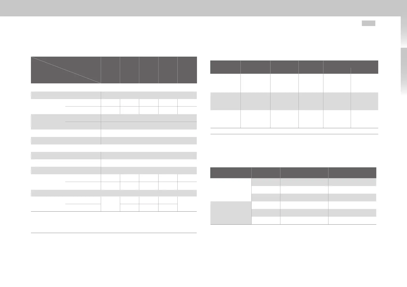
B.2.3 G393-072 to G393-170 / G397-084 to G397-210
Designation
Technical data
G393-072/
G397-084
G393-090/
G397-110
G393-110/
G397-130
G393-143/
G397-170
G393-170/
G397-210
Output motor-side
1)
Voltage 3-phase U
DC
/√2
Rated current
effective (l
n
)
Air cooling 72A 90A 110A 143A 170A
Liquid cooling 84A 110A 143A 170A 210A
Peak current
Air cooling see table B.5
Liquid cooling see table B.10
Rotating field frequency 0 ... 400Hz
Power stage switching frequency 4, 8, 12, 16kHz
DC input
DC voltage (U
DC
) nominal
2)
565V
DC
/ 650V
DC
/ 678V
DC
/ 770V
DC
Current (RMS approximation value) 1.2·I
Motor
Device connected load
3)
U
ZK
·1.2·I
Motor
Power loss at
I
N
and 8 kHz/
565VDC
Air cooling 1010W 1300W 1600W 2100W 2500W
Liquid cooling 1130W 1500W 1940W 2380W 2650W
DC link
Capacity
Air cooling
900µF
1060µF 2120µF 3180µF
4240µF
Liquid cooling 2120µF 3180µF 4240µF
1) All data referred to output voltage 400 V
eff
and switching frequency 8 kHz
2) Generated from rectified TN system with grounded neutral point and external conductor voltages 3 x 400 V AC, 3 x 460
V AC or 3 x 480 V AC with the approved Moog Servo Drive devices (MSD Servo Drive AC-AC or MSD Power Supply Unit).
Insulation voltage as per EN 61800-5-1, system voltage 277 V, overvoltage category III.
3) Approximate values
Table B.13 Technical data G393-090 to G396-170
B.3 Motor cable terminals
Feature Size 1 + Size 2 Size 3 + Size 4 Size 5
Size 6A
90 - 110A 143 - 170A
Cable connec-
tion capability
(flexible, with
ferrule)
0.25-4mm²
(AWG24 -
AWG10) *
)
0.75-16mm²
(AWG18 -
AWG6)
max. 25mm²
(AWG4)
35-95mm²
(AWG2 -
AWG4/0)
50-150mm²
(AWG3 -
AWG5/0)
Tighten-
ing torque
(Nm)
0.7 - 0.8 1.7 - 1.8 2.5 - 4.5 15-20 25-30
Recommended
crimping tool
Phoenix
CRIMPFOX6
Phoenix
CRIMPFOX6 or.
16S
Phoenix
CRIMPFOX
or similar
- -
*) With ferrule without plastic sleeve up to 6mm² possible
Table B.14 Technical data – motor terminals Size 1 to Size 6A
B.4 Current consumption of control supply
Housing variant Size max. startup current Continuous current
Air cooling
Size 1 - Size 4 6A 2A
Size 5 7A 2.5A
Size 6A 10A 8A
Liquid cooling
Size 3 - Size 4 6A 2A
Size 5 7A 2A
Size 6A 8A 2A
Table B.15 Current consumption of control supply

 Loading...


