moog
MSD Servo Drive DC-AC Operation Manual
[]
Appendix
Technical data
79
Id.-No.: CA97554-001 Date: 06/2012
to glossaryto table of contents
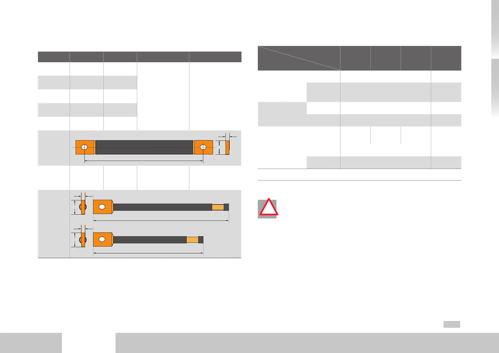
B.5 Ready made-up cables
Type L Cross-section Variant Connection
DC link
Size 1
61.5mm 42mm²
Flat copper braiding
with double shrink-fit
tube covering
Flat sheath on both
sides with hole
Ø 5.5mm
DC link
Size 2
93mm 42mm²
DC link
Size 3
133mm 42mm²
DC link
Size 4
174mm 42mm²
DC link
Size 5
193mm 42mm²
Sketch
L
4
15
DC link
Size 6A
L1 = 385mm
L2 = 345mm
30mm²
Round stranded
copper with double
shrink-fit tube covering
One side flat sheath
with hole Ø5.5mm,
second side stripped
strand
Sketch
L1
5
16
L2
5
16
Table B.16 Technical data – ready made-up encoder cables
Cable connections
DC-AC servo drive
to connect
Supply
Size 1
Size 2
Size 3
Size 4
Size 5 Size 6A
Power supply unit
Size 5
or
DC-AC servo drive
Size 1 to Size 5
Cable
Use only the
ready made-up cables supplied.
-
Tightening
torque (Nm)
2.5 -
Power supply unit
Size 6A
Cable
Use only the
ready made-up cables supplied.
95mm²
(AWG4/0)
Tightening
torque (Nm)
2.5 20
AC-AC servo drive
Cable
6mm²
(AWG9),
max. 1m
16mm²
(AWG5),
max. 1m
35mm²
(AWG2)
95mm²
(AWG4/0)
On one side ring cable lug
1)
with hole Ø5.3mm.
Tightening
torque (Nm)
2.5 20
1) In the case of ring cable lugs without insulation, the crush zone and min. 20 mm of the cable insulation should be insu-
lated fully with heat-shrink tubing.
Table B.17 Cables, cross-sections and tightening torques
!
ATTEMTION! Requirements for longer cables
• Use only the ready made-up cables supplied for the DC electrical connec-
tions between the devices.
• If extending the cable is unavoidable (such as to bypass a switch cabinet
panel or for a second DC-AC servo drive array), the DC link connection
must be made as follows:
− Cable cross-section >30mm² (copperr)
− A PE conductor of the same cross-section should run alongside and be
connected to the PE terminals of the two interconnected devices.
− The three conductors (DC+, DC-, PE) should be bundled and shielded.
− A length of 2 metres must not be exceeded.
− Only one extension may be executed in each multi-axis system.

 Loading...


