moog
MSD Servo Drive DC-AC Operation Manual
14
Id.-No.: CA97554-001 Date: 06/2012
to glossaryto table of contents
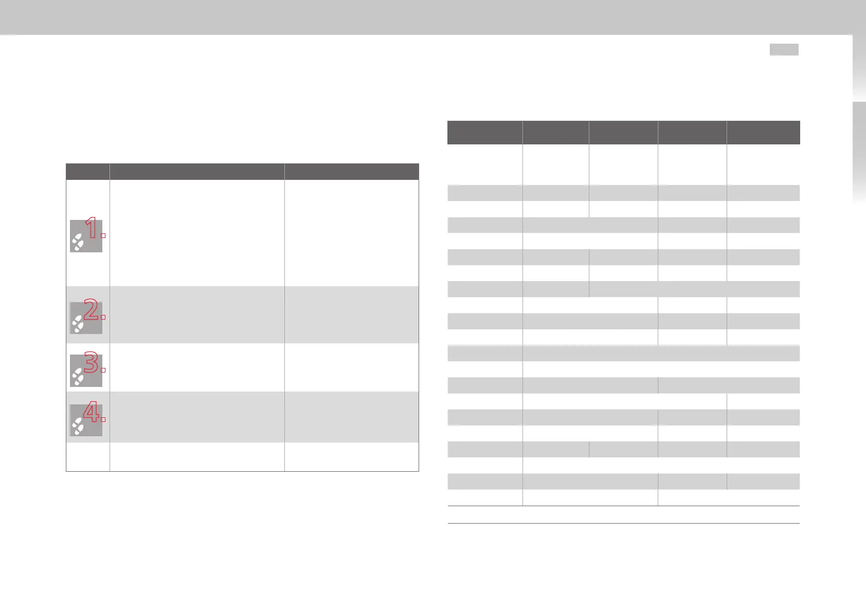
2.3 DC-AC servo drive installation
Liquid-cooled housing
Step Action Comments
Arrange the devices starting from the
supply unit to the right and/or left sorted in
descending order of power output, in order to
minimize thermal influences.
In the case of the power supply unit Size 5,
align all DC-AC servo drives in a line along the
top edge of the unit (Fig. 2.5).
In the case of the power supply unit Size 6A,
align all DC-AC servo drives 18.5 mm lower
(Fig. 2.6).
This is necessary in order to
execute the DC link using the
ready made-up cables.
For specified mounting clearances
see Table 2.1.
Mark out the positions of the tapped holes
and the pipe socket on the backing plate.
Drill holes and cut a thread for each fixing
screw in the backing plate.
Take account of the bend radius
of the connecting cables!
For hole pitch and dimensional
drawings see Table 2.2, Fig. 2.3
and Fig. 2.4.
Mount the DC-AC servo drives vertically in a
row on the back plane.
The contact area must be
metallically bright. For the DC
power supply use the supplied
ready made-up DC link cables.
When fitting the hose connections (not
supplied) in the pipe sockets, brace with
a 22mm open-ended wrench in order to
prevent damage to the device by torsion.
Ensure a perfect liquid-tight
connection (e.g. using a Teflon
sealing strip)!
Continue with the electrical installation in
section3
Dimensions and mounting distances for liquid-cooled housing
MSD Servo Drive Size 3 Size 4 Size 5 Size 6A
G397-020
G397-025
G397-026
G397-035
G397-053
G397-070
G397-084
G397-110
G397-143
G397-170
G397-210
Weight [kg] 6.5 7.5 13 32
B (width) 130 171 190 280
H (height)
1)
295 346.5 540
T (depth)
1)
224 238.5 285
A 80 120 150 200
A1 10 25 40 65
A2 60 70
C 382 406.5 581
C1 5 6 10
D 4.8 6.5 9.5
D1 48 (hole for pipe-socket)
E Direct side by side mounting, maximum 2
F
2)
≥150 ≥180
G
2)
≥300 ≥500
H1 392 418.5 600
H2 38.5 15 20
H3 75 70 54 56.5
S [inches] 3/8 (inside thread)
Screws 4 x M4 4 x M6 4 x M8
T1 74 73.5
1) Without terminals/connectors All dimensions in mm
2) The bend radius of the connecting cables must be taken into account
Table 2.2 Dimensions and mounting distances for liquid-cooled housing

 Loading...


