moog
MSD Servo Drive DC-AC Operation Manual
20
Id.-No.: CA97554-001 Date: 06/2012
to glossaryto table of contents
• Grounding
The grounding measures of relevance to the servo drive are detailed in section 3.4
on page 24.
• External components
− Place larger consumers near the supply.
− Contactors, relays, solenoid valves (switched inductors) must be wired with
fuses. The wiring must be directly connected to the respective coil.
− Switched inductors should be at least 0.2 m away from process controlled as-
semblies.
If you need more details on installation please contact the Moog Helpline (see page 50).
Step Action Comment
Identify the terminal assignment applicable
to your device.
Section 3.2 for Size 1 to Size 4
Section 3.3 for Size 5 and Size 6A
Connecct all required input and output units
to the control terminals and option interfaces
where appropriate.
Section3.7
Section3.10 and/or 3.11
Connect the encoder and motor. Sections3.12 and 3.13
Connect the protective conductor and the
supply voltages using the ready made-up
cables (DCLink).
Sections3.4 and3.6
Continue with commissioning ind section4.
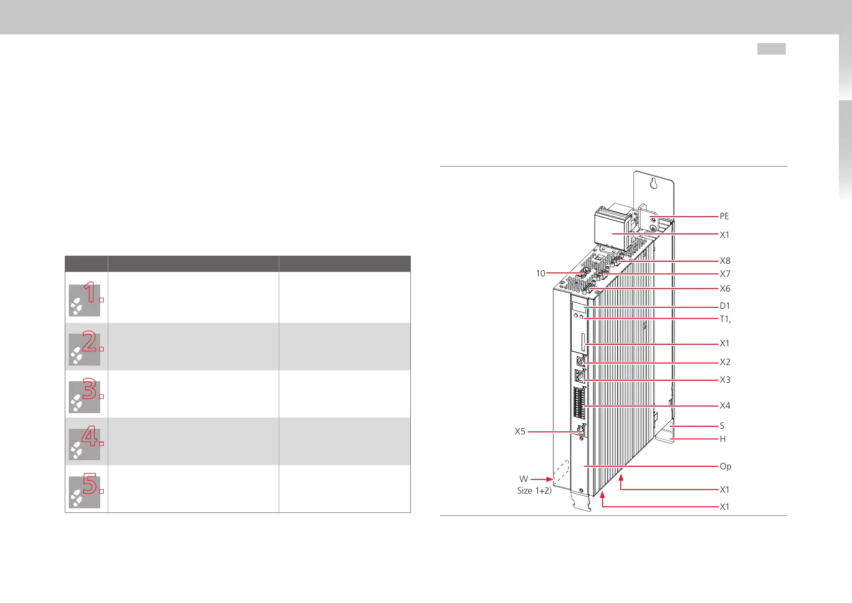
3.2 Overview of connections Size 1 to Size 4
The following shows the layout, with the corresponding positions of plugs and terminals.
To aid orientation, the connectors and terminals are labelled by abbreviations.
Fig. 3.1 Layout Size 1 to Size 4 (here: Size 1)
PE
X11
X8
X7
X6
D1, D2
T1, T2
X1
X2
X3
X4
SW (Size 3+4)
HW
Option1
X12
X13
X9, X10
X5
SW
(Size 1+2)

 Loading...


