moog
MSD Servo Drive DC-AC Operation Manual
[]
Commissioning
39
Id.-No.: CA97554-001 Date: 06/2012
to glossaryto table of contents
• Destruction of the motor
− The motors are intended for operation on the servo drive. Direct con-
nection to the mains supply may destroy the motor.
− The motor surfaces may become extremely hot. Temperature-sensitive
items should therefore not be placed on top of or attached to the mo-
tors. Protective measures may be needed to prevent touching.
− In order to avoid overheating of the motor, the temperature sensor
installed in the winding must be connected to the terminal of the servo
drive temperature monitor (X5).
− The motor brake (if installed) should be checked for fault-free function-
ing before commissioning of the motor. The optionally installed standstill
holding brake is only designed for a limited number of emergency brak-
ing operations. Use as a working brake is prohibited.
Display readout after switching on the power supply
D1 D2 Action Reaction Explanation
Switching on the
power supply
Open-loop control ready,
power stage ready, closed-
loop control disabled
Device is ready to switch
on
Table 4.2 Display D1/D2 after switching on the mains supply
NOTES:
• Inputs “ISDSH” and “ENPO”
For step 1 from table 4.3 the two inputs “ISDSH” and “ENPO” of terminal
X4 must be configured as a minimum.
• Readiness
When operating with an AC-AC servo drive as the supply, all DC-AC servo
drives in the system must be in state 2 (ready for operation) before the first
axis starts up.
• Manual mode dialog
The best way to execute step 2 from table 4.3 is via the “Manual mode”
dialog of Moog
DriveADministr Ator5. For details refer to the Online Help.
• Configuration of inputs/outputs
If step 2 is to be executed via the inputs of terminal X4, the sources for
“START CONTROL” and speed reference setpoint should be configured
accordingly in the “Inputs/outputs” subject area of
Moog
DriveADministr Ator5.
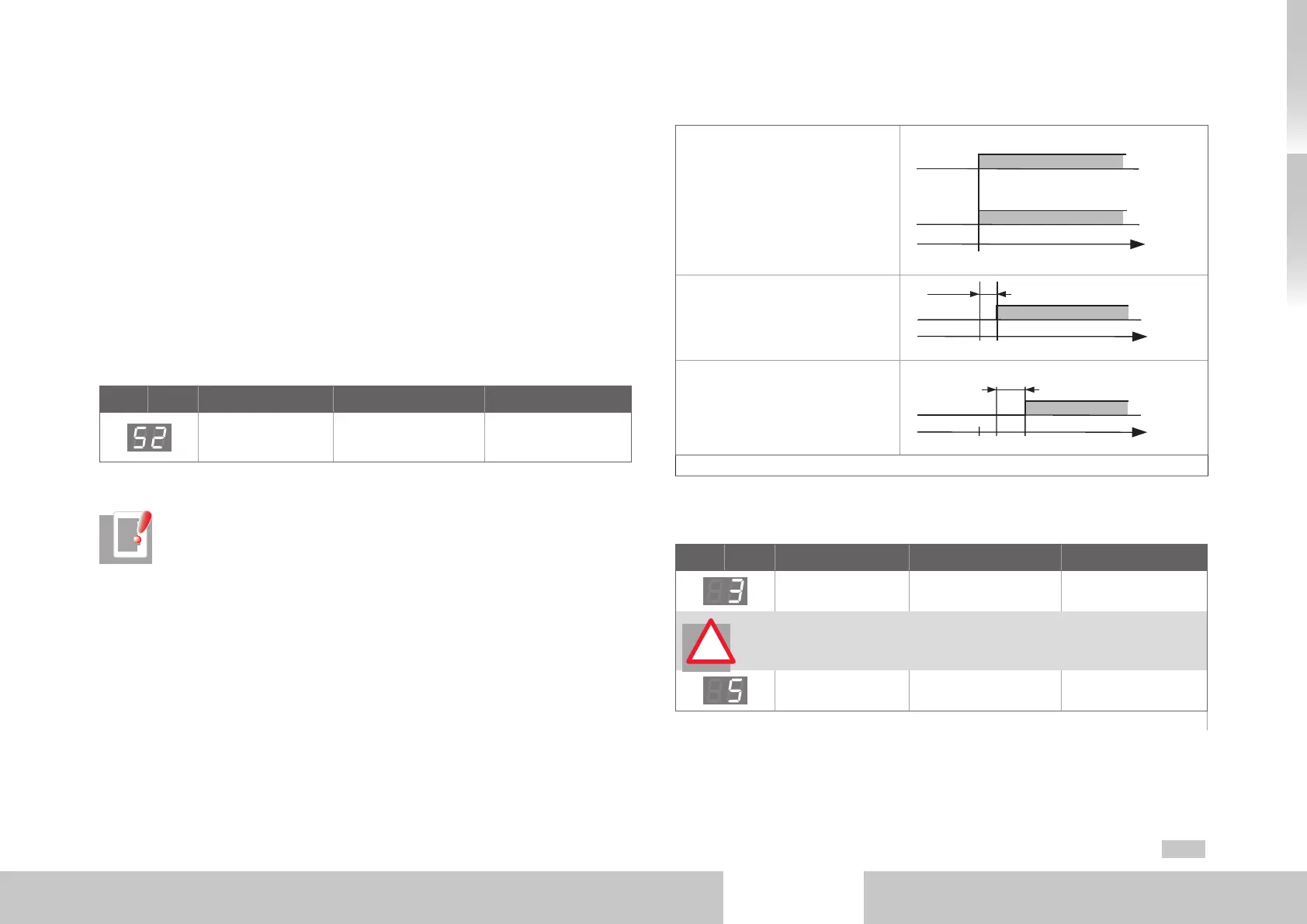
Power-up sequence to start the drive
1. Disable “STO” safety function
by setting inputs “ISDSH” and
“ENPO”
ISDSH (STO)
ENPO (STO)
1
0
t
1
0
0
2. Activate “START CONTROL” at the
earliest 2 ms after step 1 and set
the reference speed
START
t
0
1
0
≥2 ms
3. Observe your system/ plant and
check the drive response.
ON
(state 5)
t
t
0
1
0
t = Motor-dependent delay time
Table 4.3 Power-up sequence
Display readout after drive start-up
D1 D2 Action Reaction Explanation
“STO” and power stage
“ENPO” enabled
Ready for start Power stage ready
ATTENTION! Make sure before the next step, “Start enable”, to preset a
plausible setpoint value by way of the analog input! The presetting is trans-
ferred directly to the drive when motor control starts.
“Start“ enabled On
Drive powered,
control active
Table 4.4 Display D1, D2 during motor activation
For details on adapting the drive in your application refer to the
Moog
DriveADministr Ator5 Online Help and the MSD Servo Drive Application Manual.
!

 Loading...


