Digital Output SBO Relay Module
11-5
A dual selector dip switch (S3) on the DO SBO Relay module has 4 selectable positions as
described in the following tables:
Table 11-1 8 DO SBO Relay Module- Dip Switch Settings
S3
SW 1
S3
SW 2
Configuration mode
OFF OFF 12V – Relay inhibiting disabled
ON OFF Software selectable – inhibiting is set in site configuration
OFF ON 12V – Relay inhibiting disabled
ON ON 12V_DO – Relay inhibiting enabled (factory default)
Table 11-2 16 DO SBO Relay Module- Dip Switch Settings
S3
SW 1
S3
SW 2
Configuration mode
OFF OFF 12V_DO – Relay inhibiting enabled (factory default)
ON OFF Software selectable – inhibiting is set in site configuration
OFF ON 12V_DO – Relay inhibiting enabled
ON ON 12V – Relay inhibiting disabled
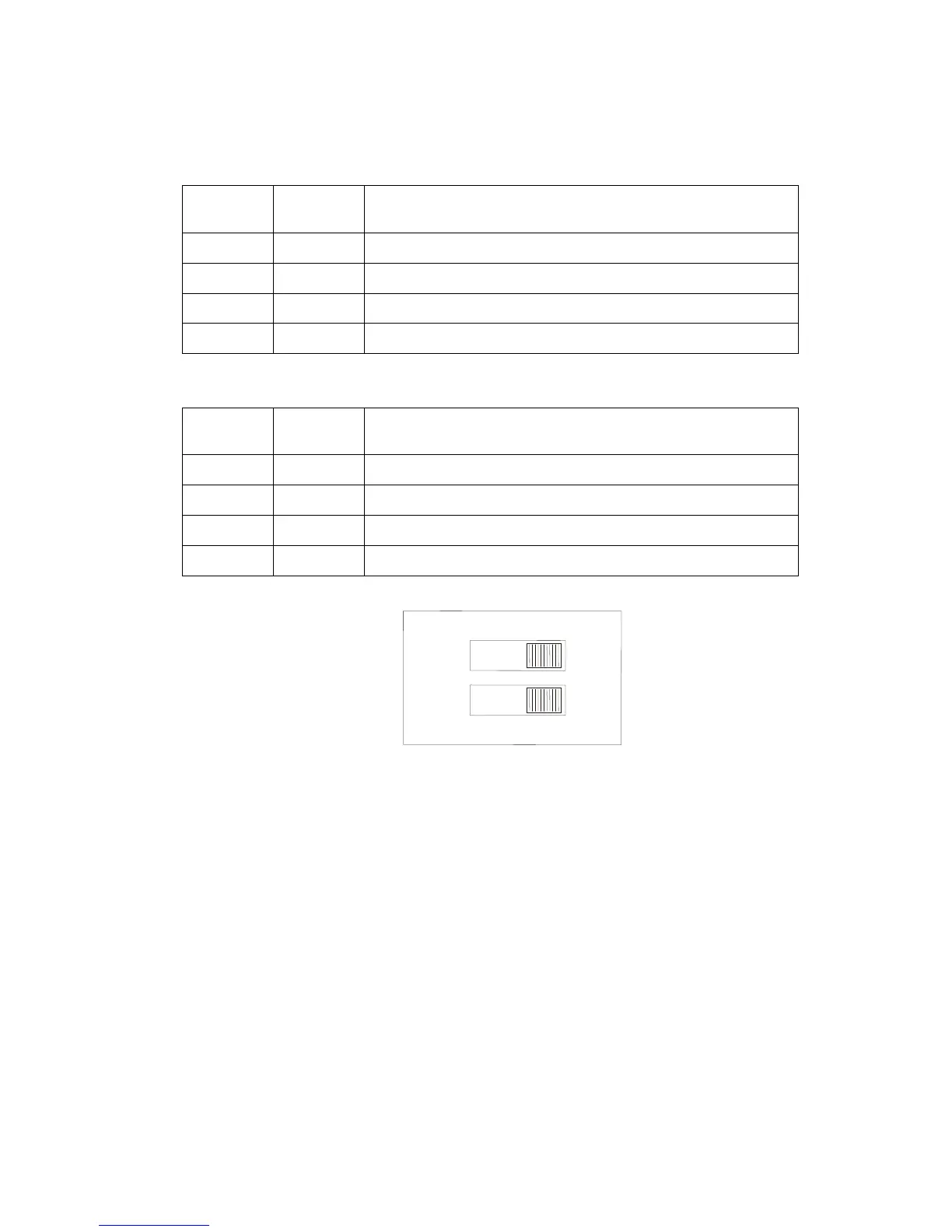
Figure 11-3 12V DO Dip Switch
When S3 is set to Software Selectable mode, the inhibiting configuration is set using the
module configuration in the STS Site Configuration (see Table 11-2 above).
Procedure 11-1 describes how to set the 12V DO dip switch to enable/disable relay inhibiting.
Procedure 11-1 How to Set the 12V DO Dip Switch to Enable/Disable Relay Inhibiting.
1) If the 2-pin TB is plugged into the 12V DO Control on the front panel of the power supply
module, unplug it.
2) Remove the DO SBO module from the slot in the rack.
3) Using a sharp tool (such as tweezers, a small screwdriver, or the tip of a ball-point pen),
through the plastic wrap set the S3 dip switch (see Figure 11-3) on the DO SBO module
board to the desired position, according to the legend in Table 11-1 (for 8 DO SBO) and
Table 11-2 (for 16 DO SBO).

 Loading...


