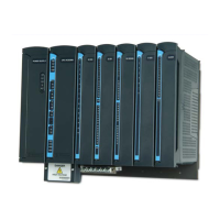
ACE IP Gateway Module
20-11
LED Name Description Status
PI1 CM Plug-in Port 1 – CM (channel
monitor)
Green LED
ON – Channel Busy (if port is in use by radio,
RS485, or RS232)
– Network Connected (if an IP plug-in is
used)
SI1 TX Serial Port 1 – TX (transmit)
Green LED
ON – Transmitting Data
SI1 RX Serial Port 1 – RX (receive)
Green LED
ON – Receiving Data
SI1 CM Serial Port 1 – CM (channel
monitor)
Green LED
ON – Channel Monitor is ON.
S2 TX Serial Port 2 – TX (transmit)
Green LED
ON – Transmitting Data
S2 RX Serial Port 2 – RX (receive)
Green LED
ON – Receiving Data
S2 CM Serial Port 2 – CM (channel
monitor)
Green LED
ON – Channel Monitor is ON
E1 LNK Ethernet Port 1 (link)
Green LED
ON – Network Connected
In case of RAM test and startup failure, see
Table 20-2 and Table 20-3.
E1 RX Ethernet Port 1 – RX
(receive)
Green LED
ON – Receiving Data
In case of RAM test and startup failure, see
Table 20-2 and Table 20-3.
PI2 TX Plug-in Port 2 – TX
(transmit)
Green LED
ON – Transmitting Data
PI2 RX Plug-in Port 2 – RX (receive)
Green LED
ON – Receiving Data
PI2 CM Plug-in Port 2 – CM (channel
monitor)
Green LED
ON – Channel Busy (if port is in use by radio,
RS485, or RS232)
– Network Connected (if an IP plug-in is
used)
D1 RX USB Device Port – RX
(receive)
ON – Receiving Data

 Loading...