February 14, 2012 6816985H01-F
4.3-14 UHF2 Detailed Theories of Operation: VOCON Functional Blocks
Most of the signals are extensions of circuits described in other areas of this manual. However, there
are two option select pins used to configure special modes: Option Select 1 and Option Select 2.
These pins are controlled by accessories connected to the universal connector. Connections to the
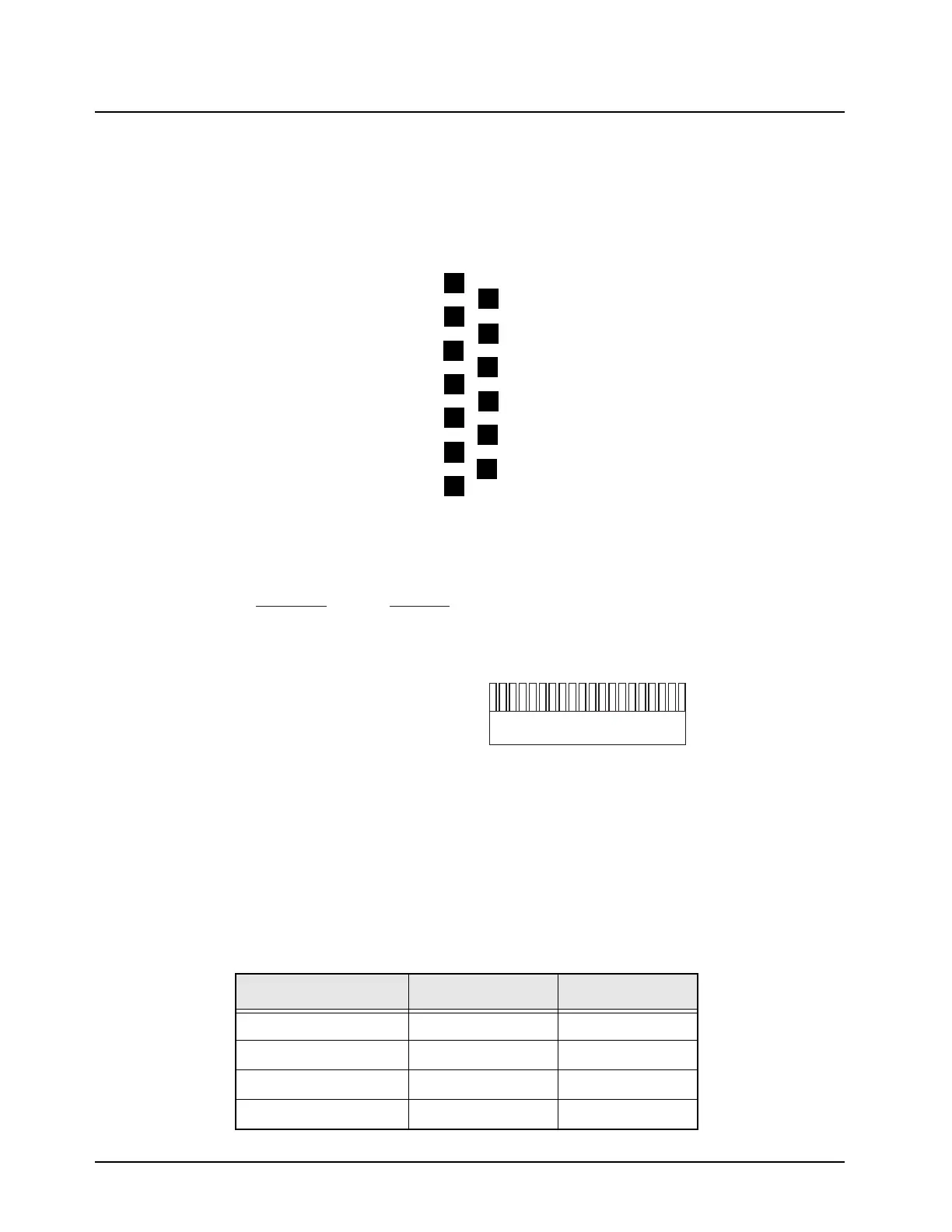
universal connector and J650 are shown in Figure 4.3-2. and Figure 4.3-3., respectively.
Table 4.3-1 outlines their functions as defined at the universal connector.
Figure 4.3-2. Universal (Side) Connector
Figure 4.3-3. VOCON Connector J650
Table 4.3-1. Option Select Functions
FUNCTION Option Select 1 Option Select 2
External PTT 0 0
No Function (Normal) 1 1
Man Down 1 0
External Speaker 0 1
OPT_SEL1
EXT_MIC
OPT_SEL2
RTS
SB9600_BUSY
RS232_DOUT/USB_D+
EXT_SPKR
12
13
1
2
OPTB+/VPP
SPKR_COM
GND
CTS
RS232_DIN/USB_D-
SB9600_DATA/KEYFAIL
MAEPF-27431-O
120
J650
Signal Name J650-Pin #
MAEPF-27467-O
GND 1, 11, 19, 20
INT_SPK+ 2
INT_SPKR- 3
OPT_SEL1 4
EXT_SPK+ 5
EXT_MIC 6
OPT_B+_VPP 7
OPT_SEL2 8
SPKR_COM 9
RTS_USB_PWR 10
LH_BUSY 12
CTS 13
RS232_TX_USB+ 14
RS232_TX_USB- 15
LH_DATA_KEYFAIL 16
NC 17
INT_MIC 18
 Loading...


