February 14, 2012 6816985H01-F
3.2-2 UHF1 Radio Power: B+ Main Board Routing
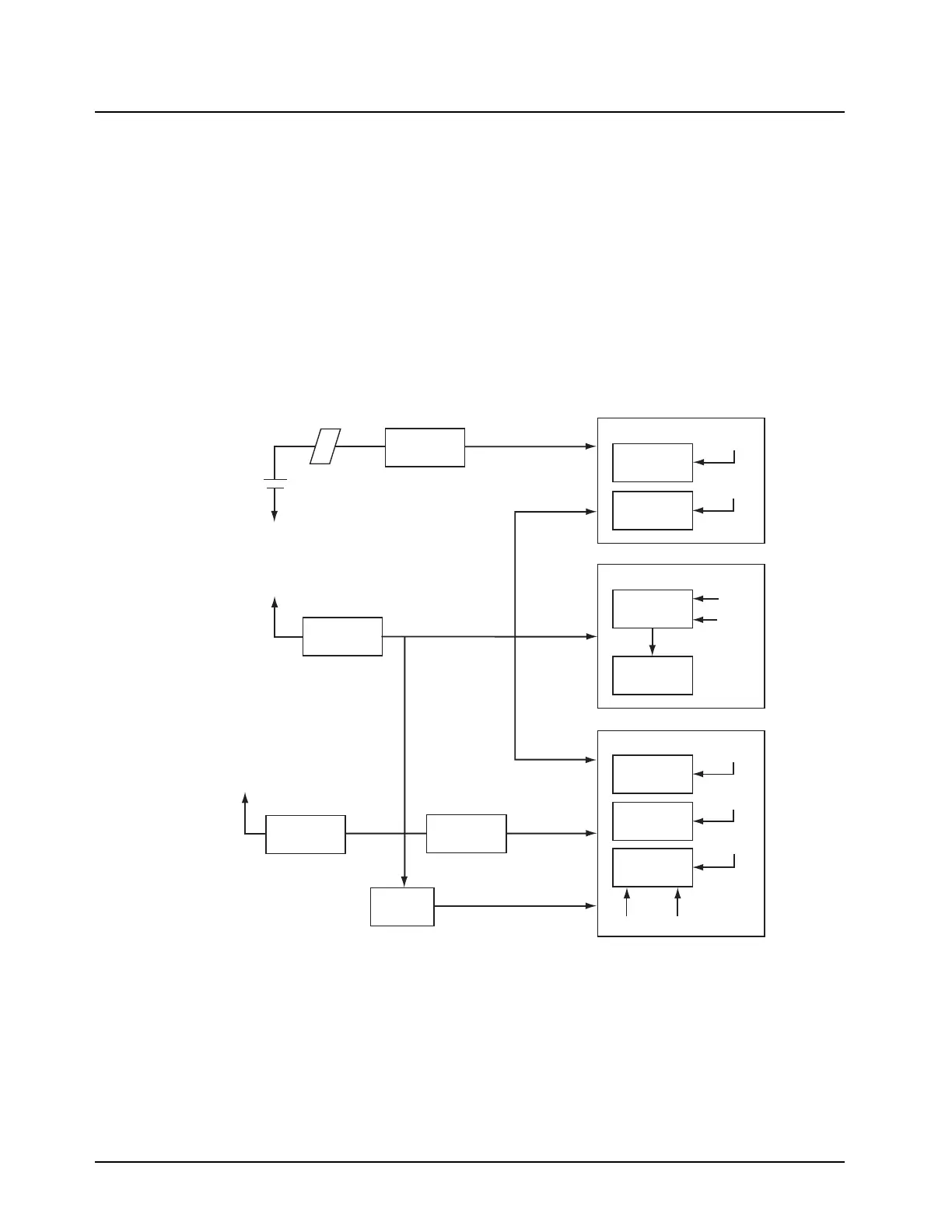
3.2.4 B+ Main Board Routing
Refer to Figure 3.2-1 and the appropriate schematic diagram in the back of this manual.
Raw B+ (7.5V) from the battery enters the radio through a 3-contact connector (B500). UNSW_B+
(through fuse F500), RAW_B+ and mechanical switch S501 derives power from it.
Through fuse F500, UNSW_B+ supplies to MAKO BAT_7V5 pin, MAKO BPLUS (PA CODEC block)
pin, Q700 and Q703. It is also routed to pin 3 of connector J601.
During the transmit mode, RAW_B+ feeds to U101 PA Driver, Q101 Final PA and U102 Power
Control IC.
During the receive mode, the linear regulator (U500) provides 5V to the mixer (U1) and the ABACUS
III IC (U401). U500 also provides 5V to the Frequency Generation Unit’s (FGU) FracN (U201).
Figure 3.2-1. B+ Routing for Main Board
Mixer
(U1)
LNA
(Q1)
ABACUS III
(U401)
5V
DIG_3VANA_3V
ANA_3V
5V
Receiver
Battery
FRAC N
(U201)
VCO’s
ANA_3V
5V
FGU
VSF
PCIC
(U102)
DRIVER & PA
(Q101)
UNSW_B+
RAW_B+
5V
5V
5V
ABACUS_3V
ANA_3V
VSW1
SW_B+
RFSW_B+
5V
Transmitter
Fuse B+
(F500)
Ferrite Bead
(E500)
TX Linear 5V
Regulator
(U500)
Analog 3V
Regulator
(U501)
Digital 3V
Regulator
(U502)
MAKO
(U701)
MAEPF-27428-O
 Loading...


