February 14, 2012 6816985H01-F
3.4-2 700/800 MHz Radio Power: B+ Routing for 700/800 MHz Band Main Board
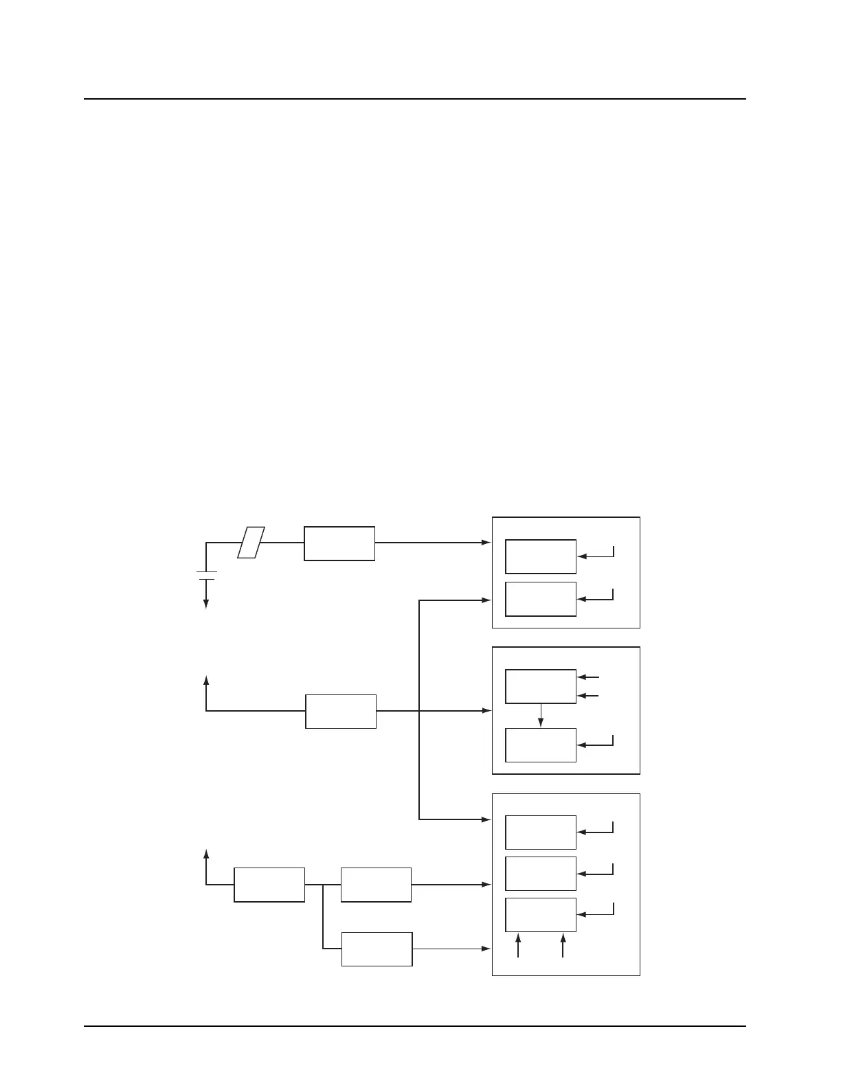
3.4.4 B+ Routing for 700/800 MHz Band Main Board
Refer to Figure 3.4-1 and the appropriate schematic diagram in the back of this manual.
Raw B+ (7.5V) from the battery enters the radio through a 3-contact connector (B500). From B500 it
is routed through a ferrite bead (E500) to the fuse (F500) where RAW_B+ is distributed to the
transmitter and the RF section is supplied by RFSW_B+.
UNSW_B+ provides power to the following:
• the mechanical switch (S501)
• the radio’s LED (D501)
and the voltage regulator (U702); then routes through the connector (J601, pin 3). U702 will be
discussed in the B+ and +5V routing for the voice encoder (vocoder) and controller (VOCON)
section.
During the transmit mode, UNSW_B+ routes through a ferrite bead (E101) to the Power Control IC
(PCIC) (U102), the RF driver (U101), through another ferrite bead (E102) to the final power amplifier
(Q101). UNSW_B+ also routes through the Field Effect Transistor (FET) switch (Q702) where it
becomes SW_B+. SW_B+ powers a 5V linear regulator (U500), which supplies 5V to the PCIC
(U102).
During the receive mode, the linear regulator (U500) provides 5V to the mixer (U1) and the ABACUS
III IC (U401). U500 also provides 5V to the Frequency Generation Unit’s (FGU) FracN (U201) and
VCOs.
Figure 3.4-1. B+ Routing for 700/800 MHz Main Board
Mixer
(U1)
LNA
(Q1)
ABACUS III
(U401)
5V
DIG_3VANA_3V
ANA_3V
5V
Receiver
Battery
FRAC N
(U201)
VCO’s
5V
ANA_3V
5V
FGU
VSF
PCIC
(U102)
DRIVER & PA
(Q101)
UNSW_B+
RAW_B+
5V
5V
5V
ABACUS_3V
ANA_3V
VSW1
SW_B+
RFSW_B+
5V
Transmitter
Fuse B+
(F500)
Ferrite Bead
(E500)
TX Linear 5V
Regulator
(U500)
Analog 3V
Regulator
(U501)
Digital 3V
Regulator
(U502)
MAKO
(U701)
 Loading...


