Chapter 7.3 UHF2 Troubleshooting Waveforms
7.3.1 Introduction
This chapter contains images of waveforms that might be useful in verifying operation of certain
parts of the circuitry. These waveforms are for reference only; the actual data depicted will vary
depending upon operating conditions. This manual is to be used in conjunction with the ASTRO XTS
2500/
XTS 2500
I/XTS 2000/ATS 3000 Digital Portable Radios Basic Service Manual (Motorola part
number 6816984H01), which uses the pass/fail service approach to radio problems.
7.3.2 List of Waveforms
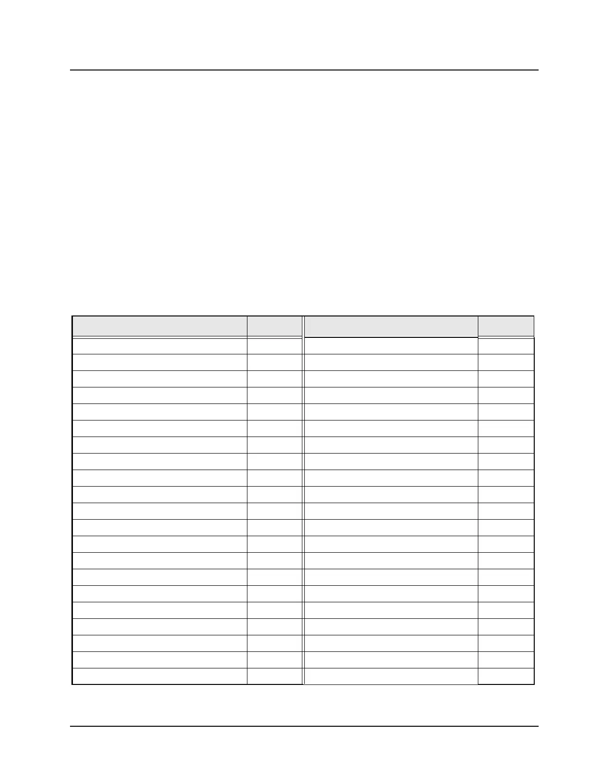
Table 7.3-1 lists each waveform and the page on which the waveform can be found.
Table 7.3-1. List of Waveforms
Waveform Page No. Waveform Page No.
Antenna Input 7.3-6 Low-Noise Amplifier Output 7.3-26
TX Signal at Harmonic Filter Input 7.3-7 Preselector 2 Output 7.3-27
Coupler RF Out 7.3-8 Mixer Out (IF) 7.3-28
TX Signal at PA 7.3-9 Crystal Filter Out 7.3-29
Coupler RF Feedback to PCIC 7.3-10 Abacus Analog 3V 7.3-30
PCIC Control Voltage 7.3-11 2nd LO Control Voltage 7.3-31
TX LO 7.3-12 2nd LO VCO Buffer Output 7.3-32
Higher Level Voltage Multiplier 7.3-13 Abacus Digital 3V 7.3-34
Superfilter Output 7.3-14 TX Audio 1 kHz Tone 7.3-35
Prescalar Input to FracN Synthesizer 7.3-15 16.8 MHz Buffer Input and Output 7.3-36
Reference Crystal Output 7.3-16 32.768 kHz Clock Outputs 7.3-37
Mod In 7.3-17 SPI B Data 7.3-38
1st LO Control Voltage 7.3-18 RX Serial Audio Port (SAP) 7.3-39
VCO Output 7.3-19 SPI Data 7.3-40
Frequency Out (16.8 MHz) 7.3-20 SPI CLK 7.3-41
RX RF Input at Antenna Switch 7.3-21 Universal Chip Select 7.3-42
Antenna Switch Bias 7.3-22 Abacus Chip Select 7.3-43
Preselector Tuning Voltage 7.3-23 RX SSI Data 7.3-44
RX RF Input after Antenna Switch 7.3-24 RX SSI Clock 7.3-45
Analog 5V 7.3-24 RX SSI Frame Sync 7.3-46
Preselector 1 Output 7.3-25
 Loading...


