EasyManuals Logo

Motorola ATS 3000 User Manual

Motorola ATS 3000
914 pages
To Next Page IconTo Next Page
To Previous Page IconTo Previous Page
Page #478 background imageLoading...
Page #478 background image
February 14, 2012 6816985H01-F
7.5-2 Troubleshooting Waveforms: RF Test Points
7.5.3 RF Test Points
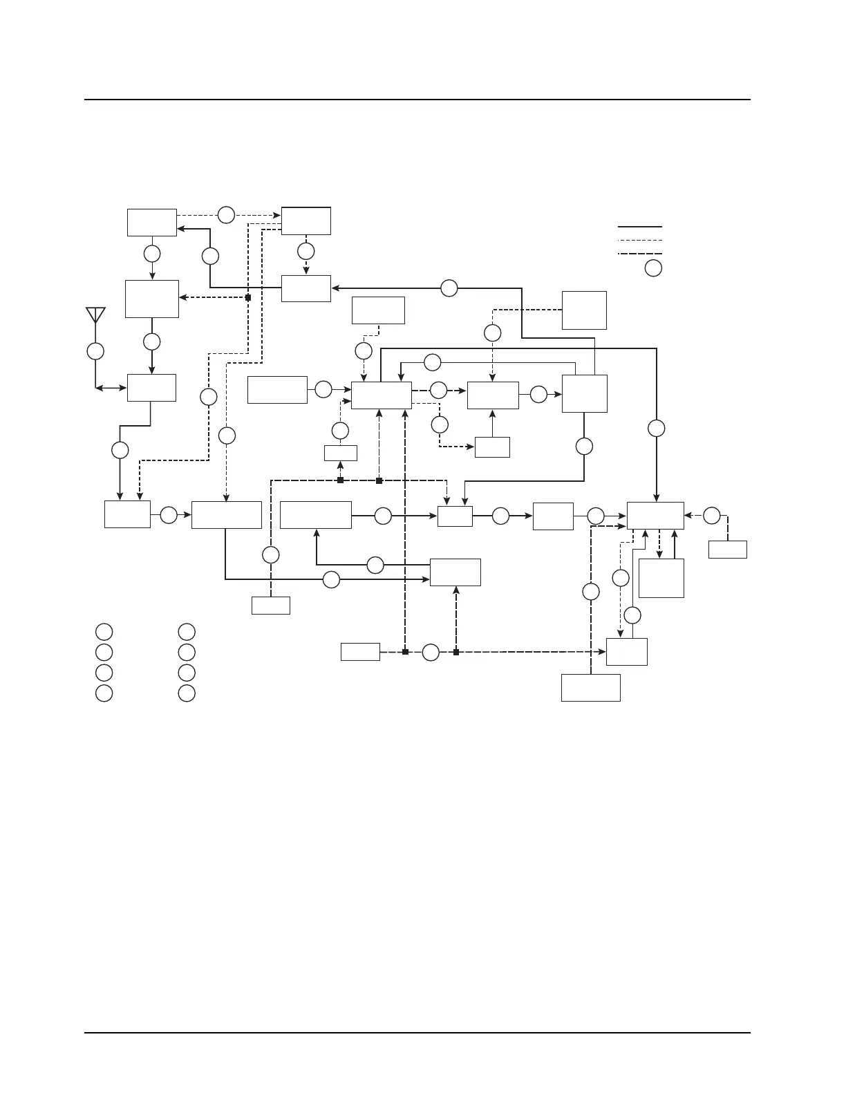
The following RF block diagram and accompanying table (Table 7.5-2) shows the location of key
probe points (PP) and test points (TP) for the XTS 2500 radio.
Figure 7.5-1. RF Block Diagram Test Points
Antenna
Switch
TX
Power
Amplifier
TRB
Level
Shifter
Harmonic
Filter
VCO
Buffer IC
Buffer
Output
Match
VCO
Antenna
Switch
Preselector #1
(Tunable)
Preselector #2
(Fixed)
Mixer
Abacus CS
Crystal
Filter
Abacus 3
3V DC
5V DC
5V DC
Sampling
Clock
Tank
2nd LO
VCO
3
4
6
7
8
9
10
#
11
1
2
19
12
20
18
21
13
14
25
26
27
15
16
17
22
23
36
24
31
28
29
30
RF
Bias
DC
Probe/Test Point
Legend
5
32
MAEPF-27353-O
DAC
16.8MHz
Crystal
LV-FractN
Synthesizer
Coupler
Detector
RF
Amplifier
Abacus 3V
Regulator
PCIC
Capacitive
Multiplier
Chip Select
35
SPI Clock
34
SPI Data
33
SSI Sync B
40
SSI FS
39
SSI Clock
38
SSI Data
37
Test Points Not Shown

Table of Contents

Questions and Answers:

Question and Answer IconNeed help?

Do you have a question about the Motorola ATS 3000 and is the answer not in the manual?

Motorola ATS 3000 Specifications

General IconGeneral
BrandMotorola
ModelATS 3000
CategoryTwo-Way Radio
LanguageEnglish

Related product manuals