February 14, 2012 6816985H01-F
5-2 Troubleshooting Procedures: Standard Bias Table
In most situations, the problem circuit may be identified using a multimeter, RF millivoltmeter,
oscilloscope (preferably with 100 MHz bandwidth or more), and a spectrum analyzer.
5.4 Standard Bias Table
Table 5-1 outlines some standard supply voltages and system clocks that should be present under
normal operation. These should be checked as a first step to any troubleshooting procedure.
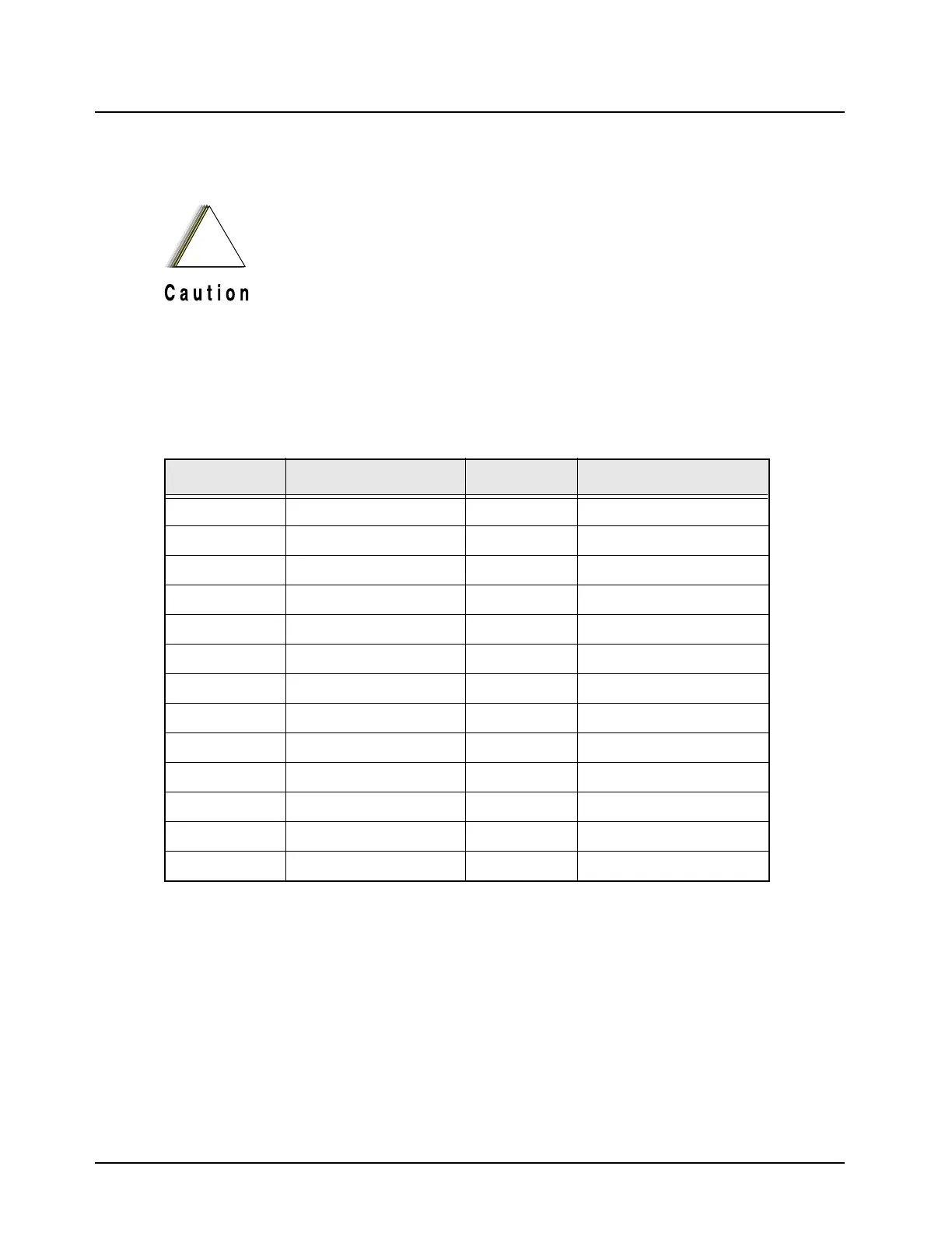
Table 5-1. Standard Operating Bias
Signal Name Nominal Value Tolerance Probe Point
Gated_32_KHZ 32.768kHz ±400ppm C742
CKIH 16.8MHz C726
16.8MHZ 16.8MHz C726
POR 2.9V dc ±5% D511, pin 2
MAKO_RESET 1.9V dc ±5% D511, pin 2
VSW1 3.6V dc ±5% R711
VSW2 2.3V dc ±5% C715
V2.9 2.9V dc ±5% L704
UNSW_B+ 7.5V dc 6-9 V dc R725
SW_B+ 7.5V dc 6-9 V dc R708
VCC5 5V dc ±5% L705
VSAVE 2.5V dc ±5% C704
RFSW_B+ 7.5V dc 6-9 V dc C730
When checking a transistor or module, either in or
out of circuit, do not use an ohmmeter having more
than 1.5 volts dc appearing across the test leads, or
use an ohms scale of less than x100.
!
Caution
 Loading...


