Chapter 8.1 VHF Troubleshooting Tables
8.1.1 Introduction
This chapter contains troubleshooting tables necessary to isolate a problem to the component level.
Use these tables in conjunction with Chapter 4.1, VHF Detailed Theories of Operation (page 4.1-1),
Chapter 5, Troubleshooting Procedures (page 5-1), Chapter 6.1, VHF Troubleshooting Charts
(page 6.1-1), and Chapter 7.1, VHF Troubleshooting Waveforms (page 7.1-1). This manual is to be
used in conjunction with the ASTRO XTS 2500/XTS 2500
I/XTS 2000/ATS 3000 Digital Portable
Radios Basic Service Manual (Motorola part number 6816984H01), which uses the pass/fail service
approach to radio problems.
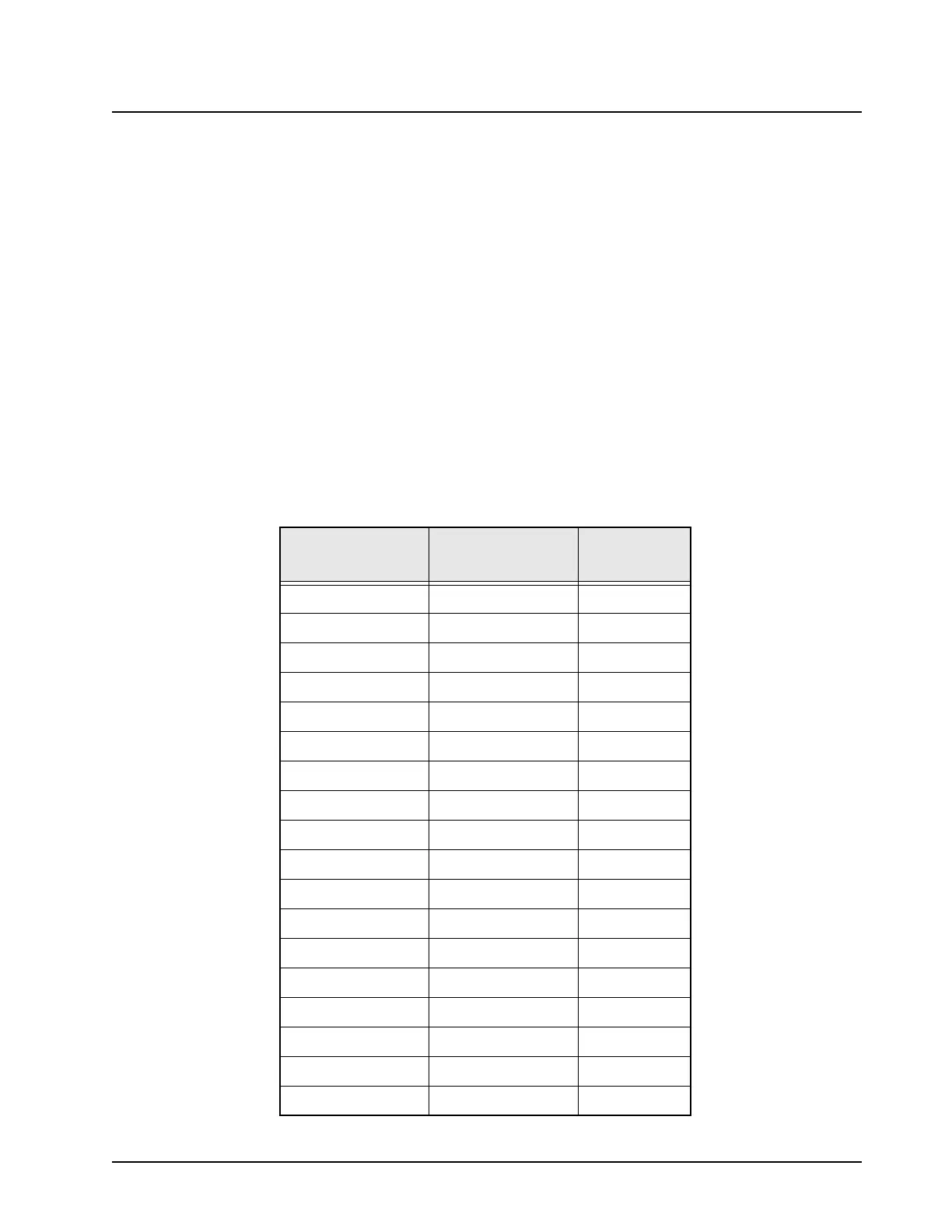
A blank entry in the “To/From” column of J601 indicates the signal is accessible only at J601.
8.1.2 Tables
Table 8.1-1. Main Board to Keypad Board Flex Assembly (J601)
J601
Pin Number
Description To/From
1 V1.875 L703
2 V2.9 L704
3 UNSW_B+ R701
4SW_B+R708
5HOST_WAKE
6 WAKEUP
7 REGISTER_SEL
8 DISPLAY_SEL
9SCKBR620
10 SPI_MOSI_B R621
11 SPI_MISO_B R622
12 SSI_CLK R616
13 SSI_FSYNC R617
14 CODEC_TX R625
15 CODEC_RX R626
16 KEYPAD_ROW0
17 KEYPAD_ROW1
18 KEYPAD_ROW2
 Loading...


