6816985H01-F February 14, 2012
700/800 MHz Radio Power: B+ and +5V Routing for VOCON 3.4-3
3.4.5 B+ and +5V Routing for VOCON
Refer to Figure 3.4-2 and the appropriate schematic diagrams in the back of this manual.
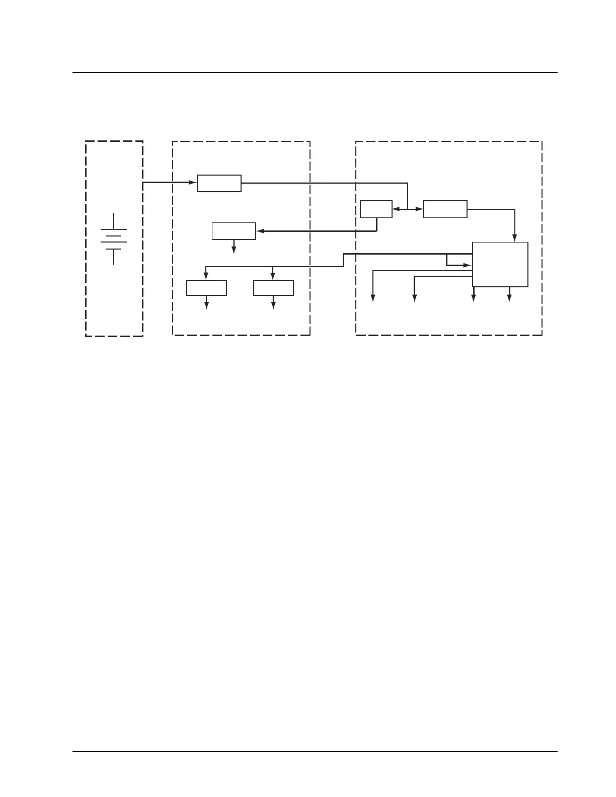
Figure 3.4-2. XTS 2500/XTS 2500I/XTS 2000/ATS 3000 DC Distribution (for all other kits)
Power for the radio is derived from a 7.5 volt battery (UNSW_B+), which is applied to the power
mosfet (Q703 and Q700) in the RF and VOCON sections respectively.
Q700 is a power mosfet switch that provides SW_B+ to the MAKO IC to U500 (the 5V regulator) in
the RF section.
The digital circuits in the VOCON section are powered from regulators located in the MAKO IC. The
MAKO IC provides five software-programmable supplies (VSW1, V1.55, V1.875, V2.9 and VCC5).
VSW1 provides voltage to the 3V regulators (U501 and U502) in the RF section. The initial and
programmed output of VSW2 (C715) is 2.3V. The VSW2 is used internal to the MAKO IC to supply
the 1.875V (V1.875) and 1.55V (V1.55) linear voltage regulators.
Battery
7.5 Volts
(Nominal)
RF Section
Fuse
U500
5 Volts
U501
U502
3 Volts
Analog Circuits
3 Volts
Digital Circuits
UNSW_B+
RFSW_B+
UNSW_B+
Q700Q703
U701
SW_B+
3.6 V (VSW1)
1.875 Volts
(V1.875)
5 Volts
(VCC5)
1.55 Volts
(V1.55)
2.9 Volts
(V2.9)
VOCON Section
 Loading...


