700/800 MHz Schematics, Board Overlays, and Parts Lists 9.4-1
6816985H01-F February 14, 2012
Chapter 9.4 700/800 MHz Schematics, Board Overlays, and Parts Lists
9.4.1 Introduction
This chapter contains the schematics, board layouts, and parts lists for the
XTS 2500/2500
I/2250/1500/2000 and ATS 3000 radios. Use them in
conjunction with the theory of operation and the troubleshooting procedures,
charts, and waveforms to isolate a problem to the component level.
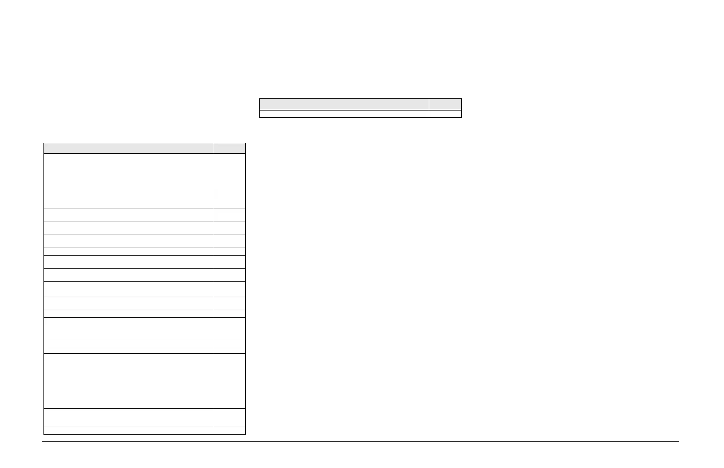
Table 9.4-1. 700/800 Schematics, Board Overlays and Parts Lists
Schematic/Board Layout Page No.
PMLF4040A/ PMLF4040B/ PMLF4040C/ PMLF4040F Top Level Schematic 9.4-2
PMLF4040A/ PMLF4040B/ PMLF4040C/ PMLF4040F Controller Interface
Schematic
9.4-3
PMLF4040A/ PMLF4040B/ PMLF4040C/ PMLF4040F Interface and
Accessories Schematic
9.4-4
PMLF4040A/ PMLF4040B/ PMLF4040C/ PMLF4040F Side Connector
Schematic
9.4-5
PMLF4040A/ PMLF4040B/ PMLF4040C/ PMLF4040F Controller Schematic 9.4-6
PMLF4040A/ PMLF4040B/ PMLF4040C/ PMLF4040F Patriot Bravo (U800)
Schematic
9.4-7
PMLF4040A/ PMLF4040B/ PMLF4040C/ PMLF4040F MAKO DC and Audio
Schematic – Sheet 1 of 2
9.4-8
PMLF4040A/ PMLF4040B/ PMLF4040C/ PMLF4040F MAKO DC and Audio
Schematic – Sheet 2 of 2
9.4-9
PMLF4040A/ PMLF4040B/ PMLF4040C/ PMLF4040F Memory Schematic 9.4-10
PMLF4040A/ PMLF4040B/ PMLF4040C/ PMLF4040F Frequency Generation
Unit (FGU) Schematic – Sheet 1 of 3
9.4-11
PMLF4040A/ PMLF4040B Frequency Generation Unit (FGU) Schematic –
Sheet 2 of 3
9.4-12
PMLF4040C Frequency Generation Unit (FGU) Schematic – Sheet 2 of 3 9.4-13
PMLF4040F Frequency Generation Unit (FGU) Schematic – Sheet 2 of 3 9.4-14
PMLF4040A/ PMLF4040B/ PMLF4040C/ PMLF4040F Frequency Generation
Unit (FGU) Schematic – Sheet 3 of 3
9.4-15
PMLF4040A/ PMLF4040B/ PMLF4040C Receiver Schematic – Sheet 1 of 2 9.4-16
PMLF4040F Receiver Schematic – Sheet 1 of 2 9.4-17
PMLF4040A/ PMLF4040B/ PMLF4040C/ PMLF4040F Receiver Schematic –
Sheet 2 of 2
9.4-18
PMLF4040A/ PMLF4040B Transmitter Schematic 9.4-19
PMLF4040C/ PMLF4040F Transmitter Schematic 9.4-20
PMLF4040A/ PMLF4040B/ PMLF4040C/ PMLF4040F RF Schematic 9.4-21
PMLF4040A/PMLF4040B/PMLF4040C/PMLF4040F/PMUF2134A/
PMUF2123A/PMUF2135A/PMUF2124A/PMUF3334A/PMUF3323A/
PMUF3335A/PMUF3324A Main Circuit Board Component Location Detail –
Side 1
9.4-22
PMLF4040A/PMLF4040B/PMLF4040C/PMLF4040F/PMUF2134A/
PMUF2123A/PMUF2135A/PMUF2124A/PMUF3334A/PMUF3323A/
PMUF3335A/PMUF3324A Main Circuit Board Component Location Detail –
Side 2
9.4-23
PMLF4040A/ PMLF4040B/ PMUF2134A/PMUF2123A/PMUF2135A/
PMUF2124A/PMUF3334A/PMUF3323A/PMUF3335A/PMUF3324A Main
Circuit Board Electrical Parts List
9.4-24
PMLF4040C Main Circuit Board Electrical Parts List 9.4-31
PMLF4040F Main Circuit Board Electrical Parts List 9.4-39
Table 9.4-1. 700/800 Schematics, Board Overlays and Parts Lists (Continued)
Schematic/Board Layout Page No.
 Loading...


