February 14, 2012 6816985H01-F
7.4-4 700/800 MHz Troubleshooting Waveforms: Main Circuit Board RF Shield Locations
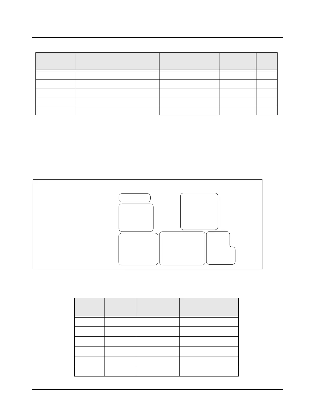
7.4.4 Main Circuit Board RF Shield Locations
Viewed from Side 1
36 Abacus Chip Select U401, pin 25 Yes. 7.4-46
37 RX SSI Data TP403 No. 7.4-47
38 RX SSI Clock TP404 No. 7.4-48
39 RX SSI Frame Sync TP402 No. 7.4-49
40 Rx SSI Sync B TP401 No. 7.4-50
PP = Probe Point
TP = Test Point
* C261 for LO Output
C266 for TX Output
C236 for Preselector Output
Note: For test/probe points indicated with the SH prefix, use an HP 85024A High Frequency Probe to detect a
signal. The probe should be placed in center of the hole located on the top of the shield. Make sure the probe does
not touch the shield or any other components.
Table 7.4-3. Main Circuit Board Side 1 RF Shields
Item
Number
Reference
Number
Motorola Part
Number
Description
1 SH401 2685089D01 Shield, ABACUS
2 SH201 2685081D01 Shield, Synthesizer
3 SH103 2685083D01 Shield, Harmonic Top
4 SH104 2685085D01 Shield, PA
5 SH205 2685086D01 Shield, VCO Top
6 SH204 2685241D01 Shield, DAC
Table 7.4-2. RF Block Diagram Probe/Test Points (Continued)
PP/TP Name Location
Under RF
Shield?
Page
1
2
4
5
6
3
MAEPF-27489-O
 Loading...


