February 14, 2012 6816985H01-F
7.3-4 UHF2 Troubleshooting Waveforms: Main Circuit Board RF Shield Locations
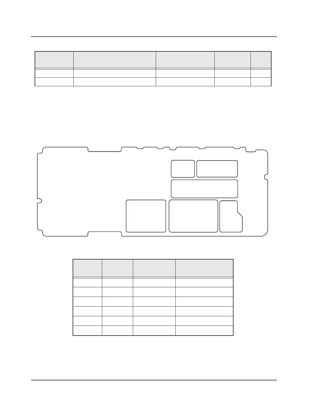
7.3.4 Main Circuit Board RF Shield Locations
Viewed from Side 1
38 RX SSI Clock SSI_CLK No. 7.3-45
39 RX SSI Frame Sync SSI_FS No. 7.3-46
PP = Probe Point
TP = Test Point
Note: For test/probe points indicated with the SH prefix, use an HP 85024A High Frequency Probe to detect a
signal. The probe should be placed in center of the hole located on the top of the shield. Make sure the probe does
not touch the shield or any other components.
Table 7.3-3. Main Circuit Board Side 1 RF Shields
Item
Number
Reference
Number
Motorola Part
Number
Description
1 SH51 2686700Z02 Shield, Mixer
2 SH402 2686698Z02 Shield, 2nd LO
3 SH102 2686701Z02 Shield, Harmonic Filter
4 SH101 2686702Z02 Shield, TX Driver
5 SH251 2616554H01 Shield, VCO Top
6 SH52 2686699Z02 Shield, Crystal IF
Table 7.3-2. RF Block Diagram Probe/Test Points (Continued)
PP/TP Name Location
Under RF
Shield?
Page
5
4
3
1
2
6
 Loading...


