February 14, 2012 6816985H01-F
6.4-12 700/800 MHz Troubleshooting Charts: Top/Side Button Error Troubleshooting Chart
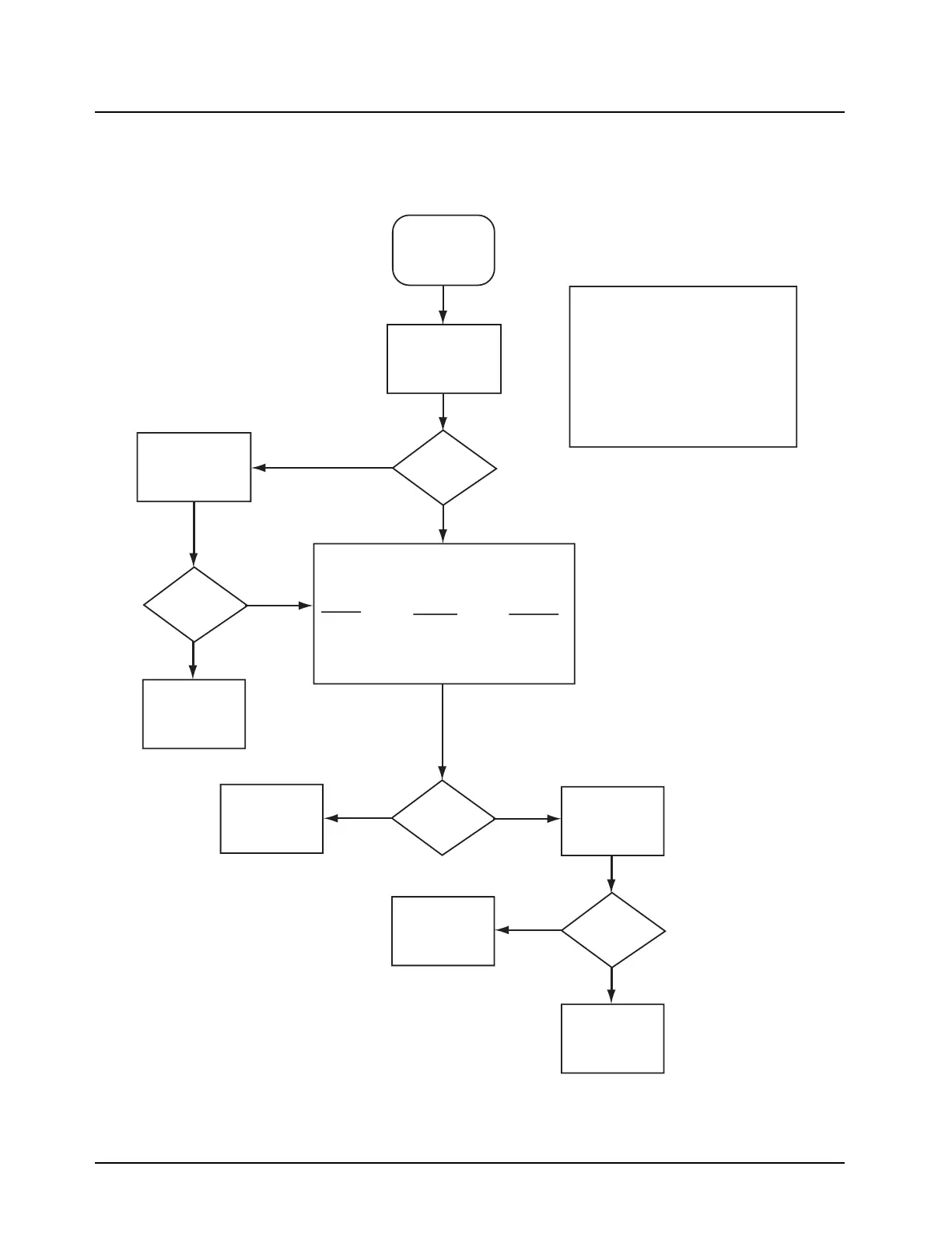
6.4.13Top/Side Button Error Troubleshooting Chart
MAEPF-27338-O
Use RSS
to enable
button
Replace
U701
Replace
buttons and/or
switch
Verify contact
with circuit
board
Using RSS,
verify problem
button is enabled
for function
Levels
correct?
Verify physical
operation of
buttons
Buttons
OK?
Button
check OK?
Buttons
Enabled?
Using a voltmeter, measure the voltages
at the resistor while depressing the
following keys:
Button
Emergency
Top Side
Middle Side
Bottom Side
Voltage
2.50V to 0V
2.70V to 0V
2.70V to 0V
3.00V to 0V
Resistor
R511
R510
R509
R508
Top/Side
Button Test
Synopsis
This chart relates to a failure in
reading the buttons. Side Button 1,
Side Button 2, or Side Button 3.
Basic failure modes are as follows:
1) Bad connection
2) Defective Switch
3) Defective MAKO IC (U701)
Verify operation
of zone knob per
"Button Test"
flow chart
No
No
Yes
Yes
No
No
Yes
Yes
 Loading...


